In this tutorial by TiFi Design, you'll learn in-depth how to create. In this tutorial by TiFi Design, you'll learn in-depth how to create. In this geometry nodes tutorial, learn how to design procedural fiber optics in Blender! You'll learn in-depth how to create, distribute, and reshape splines; capture attributes; and use those attributes to build a vibrant shader. more In this geometry nodes tutorial, learn how to design. Building Information Modeling (BIM) uses multi-dimensional, spatial models that incorporate detailed product information for the building components. Blender enthusiast and YouTuber, I make video. Just wanted to share my recent geometry nodes tutorial on how to design brilliant fiber optics. I hope you enjoy it! https://youtu. be/l-OGJml_sRQ The largest. When communicating between systems, either via the internet or via an internal network system, a medium needs to be in a place that can facilitate the transmission of data, both sending and receiving. There are numerous options available for laying down communication mediums, such as coaxial cable. The Computer-Aided Design ("CAD") files and all associated content posted to this website are created, uploaded, managed and owned by third-party users. Each CAD and any associated text, image or data is in no way sponsored by or affiliated with any company, organization or real-world item.
[PDF]
A beam splitter or beamsplitter is an optical device that splits a beam of light into a transmitted and a reflected beam. It is a crucial part of many optical experimental and measurement systems, such as interferometers, also finding widespread application in fibre optic telecommunications. DesignsIn its most common form, a cube, a beam splitter is made from two triangular glass which are glued together at their base using polyester,, or urethane-based adhesives. (Before these synthetic,. Beam splitters are sometimes used to recombine beams of light, as in a. In this case there are two incoming beams, and potentially two outgoing beams. But the amplitudes. For beam splitters with two incoming beams, using a classical, lossless beam splitter with Ea and Eb each incident at one of the inputs, the two output fields Ec and Ed are linearly related to the inputs thro.
[PDF]
Please view our full RLH price list and contact us at info@fiberopticlink. com if you have any questions or special project needs. A Fiber Optic Patch Panel, also known as an Optical Distribution Frame (ODF) or fiber termination enclosure, is a centralized hardware unit designed to manage, protect, and organize fiber optic cable connections. In an era where data speeds and network reliability are non-negotiable, the patch. fiber optic patch panel, odf, optical distribution frame, fiber distribution panel, rack mount fiber patch panel, wall mount odf, fiber termination box, 1u fiber patch panel, 24 port fiber patch panel, 48 port fiber patch panel, outdoor fiber patch panel, fiber optic odf, sliding patch panel The. Q1: What is the difference between an ODF and a patch panel? An ODF is the entire frame or cabinet managing fiber connections, while a patch panel is a modular unit inside the ODF for cross-connecting fibers. Q2: How many fibers can an ODF handle? It depends on the ODF type; rack-mount units can. ODF is used in the terminal access link of FTTH system. It is a device that splices, distributes, and splits optical fibers and provides protection and management of optical fibers. Belden offers several Fiber Patching Systems. Full patching platforms include FX ECX for LAN environments, FX UHD for high-density fiber channels and the DCX System used primarily in data centers where high amounts of fiber connections and density are the key requirements, as in optical.
[PDF]

The simplest way to do it is with a fiber media converter on either side. In its basic form, this uses electricity to convert a single Ethernet twisted-pair copper connection to fiber, and back. Running fiber internally involves extending this high-speed link from the service entry point to a centralized location, such as a dedicated media closet or network rack. This DIY effort is undertaken to maximize performance, improve aesthetics, or relocate the Optical Network Terminal (ONT) to a. Proper connection of fiber optic cables is essential to harness these benefits fully, as even minor errors can lead to significant performance issues like signal loss. This article will guide you through the necessary tools, materials, and methods on how to connect fiber optic cables effectively. The process to connect fiber optic cable to router requires careful attention to detail, but I'll walk you through every critical step with the precision and clarity you deserve. In this guide, we'll walk you through how to connect a fiber optic cable to a router safely and efficiently. Why Use Fiber Optic Internet? Before diving into the setup, let's quickly. If you want to run fiber between the two buildings, you can do it on the LAN side of your router for fairly cheap. Instead of waiting for an appointment with a technician or trying to find a time that suits, you can have everything you need for a fast fiber connection shipped to your door, so you can set it up in your own time.
[PDF]
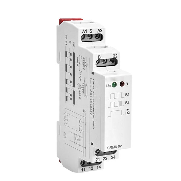
In this video, we'll walk you through the process of wiring a home distribution box with a detailed connection diagram. Whether you're an electrician or a DIY enthusiast, this guide will help you understand the basics of home electrical distribution. more Welcome to our. Learn how to install a distribution box safely and correctly. Covers wiring, placement, standards, and expert tips for a compliant setup. A distribution box is the heart of any electrical system. It takes the incoming power and safely distributes it to different circuits throughout your building. And all the switching and protective devices are installed in the. How to Estimate the Size of the Box that I Want? Can I Customize a Distribution Box? How to Choose a Suitable Electrical Distribution Box? How does a Distribution Box Work? What's the Difference Between Distribution Boxes and Junction Boxes? What is the recommended inspection schedule for. In this video, we'll walk you through the process of wiring a home distribution box with a detailed connection diagram. more Welcome to our channel! In this video. A distribution box, also known as a distribution board, electrical panel, or breaker box, is an enclosure that houses electrical components responsible for distributing electricity throughout a building. It serves as a central hub for distributing electricity throughout a building, ensuring that power is delivered safely and efficiently to all the required locations.
[PDF]

The fastest way to test a fluorescent tube is with a multimeter set to continuity mode. Each end of the tube has two pins connected by a thin filament inside the glass. If either filament is broken, the tube is dead. The whole test takes about 30 seconds per tube once you know what. This is a complete guide for testing a fluorescent light bulb with a multimeter. You don't have to be an expert in electrical work. This process measures electrical resistance to determine if the tube has suffered an internal failure before replacing the bulb or investigating the ballast. This guide provides a comprehensive understanding of the process, equipping you with the knowledge and. To test a fluorescent light bulb, observe any of the following: flickering light, low brightness, buzzing sound, delayed start, and fading color and light variation. Turn off the power to the circuit that powers the fixture and keep the leads steady to ensure accurate readings. Multimeters provide. How to Test Light Bulbs & Fluorescent Tubes with a Multimeter (Continuity Check) Is your lamp or fixture failing to light up? Before you buy a new bulb, you need to confirm if the bulb or tube itself is the problem! A simple continuity check using a multimeter can instantly tell you if the filament.
[PDF]

Testing solar panels is easy with a multimeter! To test the current, simply connect the multimeter to the panel's output. Set it to read DC current. A multimeter is an indispensable tool for anyone working with solar panels, allowing for accurate measurements and diagnostics. It empowers users to assess the performance, identify faults, and ensure optimal energy production. Without proper testing and maintenance, solar panels can suffer from. In this article, you will learn the step-by-step process of testing your solar panels using a multimeter. We will cover the essential tools you need, the specific measurements to take, and how to interpret the results. By the end of this guide, you will be equipped with the knowledge to diagnose. With just a simple tool—a multimeter —you can quickly measure your panel's voltage and current. This helps you spot issues early and keep your system running efficiently. Connect the multimeter. 🔋 Learn how to test solar panels using a multimeter — step-by-step! I'll show you how to safely check voltage, amperage, and open-circuit power, so you can confirm if your panels are producing the watts you expect. Perfect for DIY solar builders, RV owners, o. We'll also introduce the Honeytek HK78G 2000V PV Multimeter, a professional tool designed for solar testing. Honeytek, a global.
[PDF]

BER is calculated by comparing the transmitted sequence of bits to the received bits and then counting the number of errors. Whether you're a network engineer validating new inventory or an integrator preparing for deployment, knowing how to test optical transceiver modules can save time, reduce failures, and ensure SLA compliance. Unchecked optical modules can cause: Testing ensures compliance with IEEE 802. 3 and MSA. Bit Error Rate (BER) is a measure of telecommunication signal integrity based on the quantity or percentage of transmitted bits that are received incorrectly. Essentially, the more incorrect bits, the greater the impact on signal quality. It is defined as the ratio of the number of bits received in error to the total number of bits transmitted. It quantifies the error frequency caused by disturbances like statistical noise. What causes bit errors in optical data transmission? In optical systems, bit errors are. One of the most important ways to determine the quality of a digital transmission system is to measure its Bit Error Ratio (BER). Through the interpretation of actual test reports, it.
[PDF]

The core measurement procedure follows five steps: Turn on the meter and let it warm up. Most meters need a brief stabilization period before readings are reliable. Check your model's manual, but a minute or two is typical. Set the wavelength to match your light source. Fiber loss is the difference between the power when light is coupled from the transmitting end to the fiber and the power when the light reaches the receiving end. Generally speaking, when measuring the. An optical power meter measures the strength of light traveling through a fiber optic cable, giving you a reading in dBm (decibels relative to one milliwatt). The basic process is straightforward: turn the meter on, set it to the correct wavelength, clean your connectors, plug in, and read the. A power meter and light source are essential test tools that work in tandem to measure fiber optic cable loss and evaluate the quality of optical links. They provide the data necessary to quantify signal loss and pinpoint issues that could impact network performance. Here's how they work: A power. You measure optical power in dBm or insertion loss in dB. Verify light travels from transmitter to receiver. We'll give you the basic information you need and provide some printable references.
[PDF]

In this guide, I'll walk you through everything you need to know about choosing the right cable trays for your cables. Whether you're dealing with power cables, control cables, or communication cables, I'll break it down step by step. A 50 mm cable tray is used to organize and protect cable routes in industrial, commercial, and infrastructure facilities. This compact solution is suitable for power distribution lines, low-current systems, and engineering communications. Mirankul Group manufactures cable trays in Uzbekistan. Accessories for cable systems include a variety of different components necessary for the proper functioning of cable routes. They provide a structured and secure pathway for cables, ensuring organized installation and easy maintenance. Cable Trays are important for ensuring the protection of the wiring system and supporting insulated electric cables used for distribution and communication. Brilltech Engineers Pvt. Understand Your Cable Tray Requirements Before selecting a cable tray, consider the following key factors:. Selecting cable trays can feel overwhelming, especially with so many options available. But don't worry—I've got you covered.
[PDF]
In this video we show you how to dismantle a concrete telecommunications tower with a crane truck. Every health and safety measures at work were strictly comp. PTTG has experienced crews available to help when owners determine they no longer need their tanks, towers, or other structures and require them to be dismantled and removed, including scrap disposal and site cleanup. On occasion, tanks or towers cease to function or become too old to maintain. This can include towers, batteries, internal equipment, hazardous material, and communication shelter removal. We handle each project with safety and sticking to a budget in mind. Cellular tower demolition jobs can be trickier than most jobs. Legalities of what third parties have access to the site can cause issues–issues we will take care of. Our experienced team handles all aspects of decommissioning, including: • Mount & Antenna Removal – Dismantling old equipment with precision. • Microwave Decommissioning – Safely uninstalling.
[PDF]

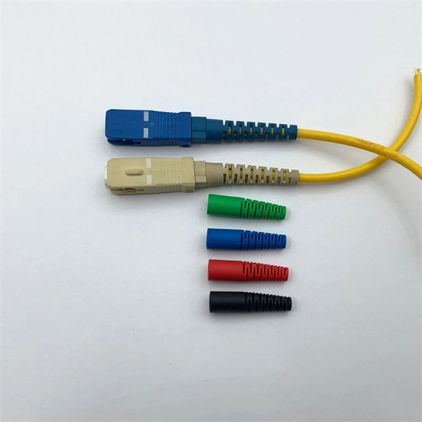
Product Range: PLC splitters, FBT splitters, fiber optic adapters, patch cords Price Range: $5 to $150 depending on splitter ratio and specs Overview: TTI Fiber is a global supplier known for quality optical components. FBT (Fused Biconical Taper) Fiber Optic Splitters. These devices splits the fiber optic signal from a single Input to two Outputs. Available in 50/50, 30/70, and 90/10 spit ratios. A fiber optic splitter is different from WDM. WDM can divide the. FBT (Fused Biconic Taper) Coupler Splitter is a commonly used fiber optic coupler and splitter for distributing optical signals to multiple output channels. FBT splitters are reliable and cost-effective, typically used for smaller split ratios like 1x2 or 1x4. The physical packaging or form factor of a splitter is crucial. FBT Coupler Splitters is widely accepted and used in passive optical networks, especially for instances where the split configuration is smaller (1×2, 1×4, etc. FBT is the traditional technology in which two fibers are placed closely together, typically twisted around each other and fused. FBT Fiber Splitter, also known as a fiber optical coupler, separates fiber optic light into many portions using a predetermined ratio. Unlike PLC splitters, FBT splitters employ distinct splitting methods and may be constructed using singlemode, multimode 62. 5, or multimode 50 fibers.
[PDF]
In this tutorial, we will show you how to fusion splice two fiber optic strands together in an easy 12 step process. The answer lies in splicing, both fusion and mechanical. Whether you're a professional technician or a DIY enthusiast, understanding the process of fusion splicing fiber optic cables is essential for maintaining high-speed communication networks. - Fiber Instrument Sales What is Fusion Splicing? How fiber optic splicers work, types, what they are used for. Steps to use this equipment and including how to test your fiber splice. The guide covers everything from basic principles of fusion splicing to detailed procedures; it is intended to provide both newbies and professionals with the necessary knowledge and skills. The operation and skills of fiber optic fusion splicing technology can be mainly divided into five steps: fiber stripping, fiber cutting, fiber melting, fiber sleeve, and fiber winding. And tools used for fiber fusion: fusion splicer; fiber cleaver; cable stripper; fiber optic stripper; alcohol;.
[PDF]
Just snap the dust cap over the electrical connector or port for which it's designed. This manual details the installation, operation and maintenance instructions for type JBDB Junction/Terminal Box (flameproof). This product is ATEX and IECEx certified to meet the requirements for hazardous location equipment. You don't need any special tools or equipment to install a dust cap. Once installed, the dust. As with most tasks, there are many ways to terminate motor leads and each one has a following who believe it is the best method. Here we will discuss some of these procedures and outline a few of the advantages and disadvantages of each. We will not consider the starting method or inter-nal. An electrical junction box is a protective housing designed to enclose and shield electrical wire connections or splices. For outdoor installations, the box must defend these sensitive splices against moisture, dust, temperature fluctuations, and physical impacts. Using a purpose-built.
[PDF]
Basic — 1,000 ft single-mode run indoors with minimal termination: Cable $0. 00/ft, Permits $150, Accessories $100. Total ≈ $2,650–$3,100. 60/ft . Buyers typically pay for fiber optic cable by length, fiber type, and installation complexity. Main cost drivers include cable grade (indoor vs outdoor, armoured), distance, and labor for trenching, splicing, and termination. This guide presents ranges in USD and practical price estimates to help. Do you also provide customisation in the market study? Yes, we provide customisation as per your requirements. To learn more, feel free to contact us on sales@6wresearch. com Any Query? Click Here. Fiber-optic cable materials typically cost $1 to $6 per linear foot, depending on fiber count and cable type. Commercial building installations with 100-200 network drops generally range from $15,000 to $30,000. Content 1 What's the Typical Price Range? 2 1. Fiber Count and Cable Construction 3 2.
[PDF]