
Run the display transceiver [ interface interface-type interface-number | slot slot-id ] [ verbose ] command to view information about the optical module on a specified interface. In optical communication equipment, an optical module (Optical Module) contains several types of semiconductor chips that work together to complete the transmission and processing of optical signals. These chips typically include laser chips, photodetector chips, driver chips, transimpedance. When the optical module on an interface is faulty, you can run the display commands to view information about the optical module. Today, we will deeply analyze the four mainstream models of 100G QSFP28 dual-fiber optical modules: QSFP28-100G-SR4, QSFP28-100G-LR4, QSFP28-100G-ER4 and. The following uses the Moduletek SFP-10G-LR module connected to a Huawei S6700 switch as an example to introduce how to read information of the connected optical module on a Huawei switch. Figure 1 Schematic Diagram of Optical Module Connected to Switch 1. Optical Module Status Check Run the. Upgrade to 100G or 400G optics and save. Cisco Transceiver Modules - Learn product details such as features and benefits, as well as hardware and software specifications. Network administrators have a major challenge determining the right Cisco SFP modules, understanding complex model numbers that directly affect network performance and stability.
[PDF]

In this guide, I'll walk you through everything you need to know about choosing the right cable trays for your cables. Whether you're dealing with power cables, control cables, or communication cables, I'll break it down step by step. A 50 mm cable tray is used to organize and protect cable routes in industrial, commercial, and infrastructure facilities. This compact solution is suitable for power distribution lines, low-current systems, and engineering communications. Mirankul Group manufactures cable trays in Uzbekistan. Accessories for cable systems include a variety of different components necessary for the proper functioning of cable routes. They provide a structured and secure pathway for cables, ensuring organized installation and easy maintenance. Cable Trays are important for ensuring the protection of the wiring system and supporting insulated electric cables used for distribution and communication. Brilltech Engineers Pvt. Understand Your Cable Tray Requirements Before selecting a cable tray, consider the following key factors:. Selecting cable trays can feel overwhelming, especially with so many options available. But don't worry—I've got you covered.
[PDF]

Cable Trays* — Max two 24 in. (610 mm) wide by max 6 in. (151 mm) deep open-ladder cable tray with channel-shaped side rails formed of 0. 54 mm) thick aluminum or min 0. In practice, cable tray dimensions are a system of interrelated measurements —width, depth, length, and material thickness—that directly affect cable fill compliance, heat dissipation, structural loading, and long-term expandability. From an engineering standpoint, cable tray dimensions are not. Perforated Cable Tray System expertly constructed from high-grade stainless steel, offering exceptional durability and resistance to corrosion. With side height 100mm. A properly designed and installed cable tray system will provide. Studs — Wall framing to consist of wood studs or channel shaped steel studs. Wood studs to consist of nom 2 by 4 in. Additional studs shall be used to completely frame. Best Size: Here, deep trays (75mm to 150mm) are used since power cables are typically thick and heavy. Data cables, such as your Wi-Fi or computer ones, are extremely sensitive. They do not get hot; however, they do not like to hang or sag. In case a data cable folds in an excessive manner, the. ect the minimum bend ra-dius for cables as they exit the bottom of the cable tray. A rung spacing of 6 to 9 inches (150 to 230 mm) is preferable when the cable tray cont d for instrumentation and control applications that require additional protec eferred to support and protect numerous small.
[PDF]

Professional Cable Tray Elbow Making | Metal Fabrication Tutorial Learn how to make cable tray elbows professionally with step-by-step guidance. This video shows metal fabrication techniques, DIY cable tray projects, and tips for perfect bends and joints. Whether you are a DIY enthusiast. The method for producing bridge bend elbows is as follows: Take a 90-degree cable tray bend elbow as an example, and apply the same principles for 45-degree bends accordingly. The length of the bottom side (bottom diagonal) after bending the cable tray should be equal to the width of the cable. This manual is designed to guide workers through the detailed production process of ladder cable trays, including the manufacture of horizontal elbows, tees, crosses, reducing bends, and vertical bends, with emphasis on precision, safety, and quality control. What's Involved in Producing Ladder. The bends, tees, crosses, risers and reducers of wire mesh cable tray can be easily and quickly made live at the project by using a bolt cutter. Since the jaws of the bolt cutter drags a layer of zinc across the cut end and forms a protective layer. When a wire cable tray is cut, the fact that a. How to bend 22. 5 DEGREE OF CABLE TRAY 3 LA. How to bend 90 degree of cable tray 3 line with the same distance :// • HOW TO BEND 90 DEGREE OF CABLE TRAY 3 LINE. Enjoy the videos and music you love, upload original content, and share it all with friends, family, and the world on YouTube.
[PDF]

Typical rates range from $0. 00 per ft depending on terrain, access, and required precision for termination. Basic — 1,000 ft single-mode run indoors with minimal termination: Cable $0. 00/ft, Permits $150, Accessories $100. Total ≈ $2,650–$3,100. Fiber-optic cable materials typically cost $1 to $6 per linear foot, depending on fiber count and cable type. Commercial building installations with 100-200 network drops generally range from $15,000 to $30,000. Single-mode fiber costs less per foot than multimode fiber, but it requires more. Buyers typically pay for fiber optic cable by length, fiber type, and installation complexity. Main cost drivers include cable grade (indoor vs outdoor, armoured), distance, and labor for trenching, splicing, and termination. This guide presents ranges in USD and practical price estimates to help. The cost per foot of fiber optic cable is now the lowest it's been since 2021. Labor dominates the installed price. Here is the 2026 benchmark for cost of laying fiber optic cable per foot by method: Open trench (lawn/field): $0. 80 per ft – fastest, lowest cost. Directional boring (road. Single-mode fiber (OS2): This is the industry workhorse. In 2025, the base glass price has stabilized. You are looking at $0. The price swing usually depends on the fiber count (e., 12-core vs 96-core) and brand. This article breaks down the price landscape and provides.
[PDF]

Step-by-step guide on connecting an inverter to your distribution board for uninterrupted power supply. The process begins with turning off the main power supply to ensure safety. Next, choose an inverter with a suitable capacity to handle your power needs, ensuring it matches the. In this article, you will find information about connecting inverter to distribution box: essential safety tips, step-by-step guidance, and common mistakes that often lead to inverter failure, so that you can avoid them. Last Updated on September 17, 2025 by June The most extensive use of inverter. Connecting an inverter to a distribution board allows you to harness stored energy from batteries or solar panels for powering electrical devices in your home. This setup provides backup power during outages and can also contribute to energy savings by utilizing renewable energy sources. This guide. In this video, we'll guide you through the process of wiring a UPS (Uninterruptible Power Supply) or inverter for your home or office. By following a few simple steps, you can easily learn how to connect an inverter DB wiring diagram. Connecting an inverter DB wiring. Scroll to the bottom of any page to find a sun or moon icon to turn dark mode on or off! I'm not an electrician and do not want to screw this up. What type of wiring do I need to connect the inverter to the distribution box? I have a 1*60A 4*20A FL+LS distribution box with a Sungold Power 5000W 48V.
[PDF]

The compact 1 port ftth fiber termination box can hold 2 cores splicing, termination and coil up to 30 meters long for cable management in FTTH network. The 1 port fiber termination box is available for fiber optic cable coiling, it is great to connect optical cable and pigtail and protect fiber splices from damage. It is small, lightweight, and offers the function of fiber splicing, storage, and termination, mainly used in residential buildings. The maximum distance for single mode fiber optic cable can extend up to several hundred kilometers, making it ideal for long distance data transmission. One type of single mode fiber is known as “G. 652,” which is commonly used in telecommunications networks. Here are some general guidelines: 1. The shorter distance accounts for the. A fiber optic distribution box (FDB) is a protective enclosure for managing fiber optic cables. It organizes connections, splices fibers, and distributes signals in networks like FTTH (Fiber-to-the-Home) or FTTB (Fiber-to-the-Building). It acts as a central point for terminating, splicing, and distributing these cables, providing necessary protection and. The Fiber Optic Association, Inc. (FOA) was founded in 1995 to help develop the workforce to build the fiber optic networks to support a rapid expansion in communications and the Internet. The charter of the FOA was to promote professionalism in fiber optics through education, certification, and.
[PDF]

This is a simple video showing how to install a 850nm fiber optic link using SFP transceivers between 2 10 Gigabit backbone switches. Covers transceiver inst. As a leading provider of fiber optic solutions, Weunion offers a wide range of SFP-compatible products, including optical transceivers, DAC/AOC cables, LC patch cords, and MPO/MTP assemblies. This guide explores the essentials of SFP connectivity, installation best practices, and how Weunion's. These transceiver modules are hot-swappable input/output (I/O) devices that plug into 100BASE, 1000BASE and 10GBASE ports (for SFP+), which connect the module port with the fiber-optic or copper network. This document contains these sections: The SFP transceiver modules are hot-pluggable I/O. An optical module is an optoelectronic conversion device that transmits data by converting electrical signals into optical signals. Common types of optical modules include SFP, SFP+, SFP28, QSFP, QSFP28, etc. Different types of optical modules have different performance parameters such as speed. The 1310 nm WWDM solution, 10GBASE-LX4, requires the use of a mode-conditioning patch cord on multimode fiber to achieve its specified range of operating distances. more Audio tracks for some languages were automatically generated. Learn more This is a simple. One of the most widely deployed optical solutions for short-distance 10G links is the multimode SFP+ transceiver, commonly referred to as a 10GBASE-SR module.
[PDF]

Learn how to install a distribution box safely and correctly. Covers wiring, placement, standards, and expert tips for a compliant setup. It takes the incoming power and safely distributes it to different. In this video, we'll walk you through the process of wiring a home distribution box with a detailed connection diagram. more Welcome to our channel! In this video. Whether you are an electrical contractor or a construction brigade, knowing how to properly and safely install distribution boxes is the basis of ensuring the safe operation of the entire system. It serves as a central hub for distributing electricity throughout a building, ensuring that power is delivered safely and efficiently to all the required locations. In modern electrical systems, cable distribution boxes (also known as electrical distribution boxes or distribution boxes) play a crucial role as the key hub for managing, distributing, and protecting circuits. Whether it is residential buildings, commercial facilities or industrial sites, the. In this guide, we will break down the key elements involved in connecting the main power supply to your home, providing a clear path for a successful setup. We will focus on the critical parts of the system, from basic components to step-by-step assembly procedures. Whether you are looking to.
[PDF]
Den här guiden går igenom allt du behöver känna till när du vill koppla din egen router till fiber, vilka alternativ som finns, vilka inställningar som krävs och hur du felsöker om något inte fungerar som det ska. However, setting up a fiber optic connection to your router can seem daunting if you're unfamiliar with the process. In this guide, we'll walk you through how to connect a fiber optic cable to a router safely and efficiently. Why Use Fiber Optic Internet? Before diving into the setup, let's quickly. Setting up a fiber internet connection requires understanding key hardware components and following a specific connection sequence to establish your home network. This comprehensive guide combines industry standards with field-tested practices to ensure you achieve a rock-solid.
[PDF]

Average Optical Power: How bright the light is (measured in dBm). Too dim? Your signal gets lost in the fiber. Extinction Ratio: The difference between “on” (1) and “off” (0) light power. A higher ratio = cleaner signals. Transmitter Side: An electrical signal hits a laser diode (LD) or LED, which spits out light. Receiver Side: Light enters a photodetector (like a tiny solar cell), which turns it back into electricity. A built-in amplifier boosts the signal for your. The average transmitted optical power refers to the optical power output by the light source at the transmitting end of the optical module under normal working conditions, which can be understood as the intensity of light. In communication, we usually use dBm to represent optical power. However, in practical use, we adopt the average Tx power. The transmission power is related to the. This article provides an in-depth analysis of two key performance indicators of optical modules: transmitter power and receiver sensitivity. Transmitter power characterizes the average optical power output from the laser under rated conditions, while receiver sensitivity indicates the minimum. An optical module is a connecting module that serves as an optical-electrical conversion device. At the receiver end, the optical signals are reconverted into electrical.
[PDF]

In today's video, we'll be unboxing the 9-Port Power Supply Box and demonstrating how to connect the cables to provide power to CCTV cameras. A CCTV power supply box sends power to all your cameras from one place. It helps keep things neat and makes your system easier to manage. In this guide, you'll learn how to install it step by step, choose the right type, avoid common problems, and keep your system running safely. Power supply boxes for CCTV are typically used in multi-camera installations instead of using single power adapters for each camera. The process is almost exactly the same if you. Installers of surveillance systems may simply control the power to various CCTV cameras using a CCTV power supply box, also known as a power distribution box (usually at the location of the DVR). This enables a cleaner camera installation. Surge protection can be accomplished in two ways. The power supply box is specifically used to transfer power requirements for all cameras plugged in on the system, to work. Security cameras use RG59U coax siamese wire or CAT5e networking cable to transmit video. Whether you are installing a power box for a new or existing camera system, it is important to understand how to connect cameras to a CCTV Power Supply Box. DC current is polarized meaning it has two leads, a.
[PDF]
In this tutorial, we will show you how to fusion splice two fiber optic strands together in an easy 12 step process. The answer lies in splicing, both fusion and mechanical. Whether you're a professional technician or a DIY enthusiast, understanding the process of fusion splicing fiber optic cables is essential for maintaining high-speed communication networks. - Fiber Instrument Sales What is Fusion Splicing? How fiber optic splicers work, types, what they are used for. Steps to use this equipment and including how to test your fiber splice. The guide covers everything from basic principles of fusion splicing to detailed procedures; it is intended to provide both newbies and professionals with the necessary knowledge and skills. The operation and skills of fiber optic fusion splicing technology can be mainly divided into five steps: fiber stripping, fiber cutting, fiber melting, fiber sleeve, and fiber winding. And tools used for fiber fusion: fusion splicer; fiber cleaver; cable stripper; fiber optic stripper; alcohol;.
[PDF]

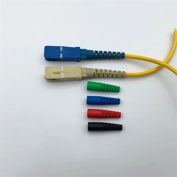
Given the access to a fusion splicer, you can splice the pigtail right onto the cable in a minute or less, which greatly speeds the splicing and saves significant time and cost spent on field termination. A fiber optic pigtail is a short length of optical fiber cable with a factory-terminated connector on one end and a bare, exposed fiber on the other. Unlike a patch cord—which has connectors on both ends—the bare fiber end of a pigtail is designed to be permanently spliced (either by fusion or. The Contractor tasked to perform testing or splicing on any fiber optic cable will follow these testing standards to fulfill their contractual obligations. The Contractor must utilize the correct equipment and testing techniques to gain acceptance, or the work cannot be approved. While for mechanical fiber optic pigtail splicing, it precisely holds a fiber optic pigtail. Fiber optic fusion splicing is on the rise and Corning's Pigtailed Splice Cassettes enable faster field splicing and easy modular management of connectorization within the housing. Pre-routed and preloaded, pigtailed splice cassettes reduce installation time by up to 40%. Today, fusion splicing. Next, we will introduce three common types: SC, FC, ST fiber optic pigtails. 5mm pre-radiused ferrule which is made of zirconia or stainless alloy.
[PDF]

In this video, we'll walk you through the process of wiring a home distribution box with a detailed connection diagram. Whether you're an electrician or a DIY enthusiast, this guide will help you understand the basics of home electrical distribution. more Welcome to our channel! In this video. Single Phase wiring installation is the most common wiring in residential buildings. In Single Phase supply (230V in UK, EU and 120V & 240V in the US & Canada), there are two (one is Line (aka Phase, Hot or Live) and the other one is Neutral) incoming cables from the utility poles to the kWh energy. A distribution board or distribution box is where the main power supply is distributed to multiple loads. And all the switching and protective devices are installed in the distribution box. Single Phase Distribution Box generally consists of Double Pole MCBs, Single Pole MCBs, and RCCBs. An electrical panel box, also known as a breaker box or a distribution board, is a crucial component of any electrical system. It serves as a central hub for distributing electricity throughout a building, ensuring that power is delivered safely and efficiently to all the required locations. What is Distribution Board? Distribution board.
[PDF]
