This guide provides instruction on how to install and configure your MS130R series switch. For more switch installation guides, refer to the switch installation guides section on. This guide provides step-by-step instructions for installing two common types of industrial switches: rack-mount, and DIN-rail switches. Choose the Installation Location: Select an appropriate spot on the DIN rail for mounting. This chapter describes how to start your switch and how to interpret the power-on self-test (POST) that ensures proper operation. No prior experience needed—just follow along and you'll have your switch installed and running in minutes. more In this video you'll see a complete, step-by-step guide to mounting. This typeface indicates command syntax, or represents information as it is displayed on the screen. When you see the word enter in this guide, you must type something, and then press the Return or Enter key. Do not press the Return or Enter key when an instruction simply says type. Here, we explore the four most common installation methods for industrial switches: Desktop installation is the most straightforward approach— placing the switch like a small box directly on a table, control panel surface, or equipment rack without extra fixtures. Simple setup: No tools required.
[PDF]

show interface - To view the configured IP address on the switch. These are the various commands referenced in this document: Updated Grammar and Formatting. Finding the IP address of your network switch is crucial for a variety of tasks, from configuring its settings to troubleshooting network connectivity issues. While it might seem like a technical hurdle, several straightforward methods can help you uncover this essential piece of information. This article provides a comprehensive guide to locating the IP address of a Cisco switch, covering various methods and tools available to network administrators and. Knowing the IP address of your switch is essential for network troubleshooting, configuration, and management. However, finding the IP address of a switch can sometimes be challenging, especially if you don't have access to its documentation or network infrastructure details. In this article, we. This guide will go over how to find the IP address of the M4300 & M4250 and how to access the web interface of the switch. Check the DHCP server to find the new lease from the switch. VLAN 1 default IP address. Two of them are Cisco ones the third one is a D-Link. My predecessor was managing them, unfortunately, when I inherited them I got zero information about it and. Configure the IP address on the switch. Do the next steps to set the system parameters on Catalyst switches that run Cisco IOS software. For details on how to connect to the Console ports of the.
[PDF]
You can run the display arp command to view IP addresses and interfaces of servers directly connected to a switch. Since it is based on arp, it does only work for devices having an ip address in the network segment where you use that feature. So if not used in the management network, it may only be applied with L3 Switches. As far as I know it is not really the case. Ip device tracking can work on L2. Finding the IP address of your network switch is crucial for a variety of tasks, from configuring its settings to troubleshooting network connectivity issues. While it might seem like a technical hurdle, several straightforward methods can help you uncover this essential piece of information. This guide will go over how to find the IP address of the M4300 & M4250 and how to access the web interface of the switch. VLAN 1 of the switch is configured by default to receive DHCP. VLAN 1 is configured by. Is there a command that I can use through Putty to figure out the IP new IP address of the switch? Thank you! Edit: The switch is still isolated and is not connected to anything other than the workstation that I am using to configure it. Just hook back up to the COM port and look. Network switches are integral components of modern computer networks, facilitating efficient data transmission and connectivity among multiple devices. The INTERFACE field displays switch.
[PDF]
This section includes all PoE enabled Industrial switches available, including managed models and specific application models like vehicle or substation compliant units. Check each product page for other buying options. Shop products from small business brands sold in Amazon's store. Learn more Need help? Industrial-grade PoE switches for demanding. POE Industrial Ethernet units at Plant Technology USA make Power over Ethernet solutions even more efficient and cost effective. Not only are these de. Read more Find the best Industrial Ethernet Equipment for your project. US-based Customer Support. These rugged, fanless platforms support both Gigabit and 10/100 Mbps Ethernet and offer a selection of fixed-fiber, or SFP uplink. We provide a wide range of PoE/PoE+/PoE++ switches with up to 90 W output per port to deliver high-speed data transmission while powering high-power devices over long distances. With an industrial-grade design, our PoE switches provide surge protection of 4 kV per LAN port. Additionally, Smart PoE. In addition to transmitting network data, a PoE Switch has a built-in Power over Ethernet injector to supply up to 100W Power over Ethernet (PoE) to standards-based 802. 3bt compliant devices such as IP cameras, VoIP phones, and wireless access points. When connecting network.
[PDF]
In part two of the 7-part series on how to wire a switch, I explain and demonstrate how to install the cables into a multi-gang box. The video focuses on steps that will both save time and simplify the process. In this video, we'll walk you through the process of wiring a home distribution box with a detailed connection diagram. Whether you're an electrician or a DIY enthusiast, this guide will help you understand the basics of home electrical distribution. Part of my job as a professional electrician is keeping my work neat and organized. A tidy work box makes it easier to install lights, switches, and outlets, and it helps future electricians to see what's going on inside the. Learn how to install a distribution box safely and correctly. Covers wiring, placement, standards, and expert tips for a compliant setup. A distribution box is the heart of any electrical system. It takes the incoming power and safely distributes it to different circuits throughout your building. If you're looking to install a switch box in your home or office, it's important to understand the process involved and the key steps to follow. And all the switching and protective devices are installed in the. According to NEC (National Electric Code: Article 1 00-Definitions), a Main Panel (also known as Panelboard, load center, breaker box and distribution board etc. ) is a cabinet or cutout box which contains on controlling and protective devices (such as circuit breakers, fuses, switches etc.
[PDF]
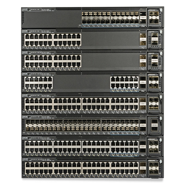
There are 48 bicolor LEDs (green/amber) for the first 48 SFP+ ports and 16 tricolor LEDs (green/amber/white) for the SFP-DD ports. The last set of LEDs pulse once in white before indicating the FC port status in green or amber. When it blinks white twice, it shows the status of the second port of the SFP-DD. The port status LEDs for the FC ports are arranged left and right to correspond to the upper and lower ports respectively in each pair. LEDs on the port side of the switch Table 1. LEDs on Cisco Catalyst 9500 Series Switches 1 Available only on switches with 10G ports. System LED Indicator System is not operational. System is operating normally. As a group or individually, the LEDs show information about the switch and about the ports Preventing Overload - Each port that provides PoE has a maximum power it can deliver. Three LEDs are used on each port. Ports on the Cisco Catalyst switch do not have LEDs. Not the question you're searching for? Each. Number of LEDs per port - Ports that cannot be split; for example, 1G ports must have 1 LED per port. Location - A port LED should be placed right above the.
[PDF]
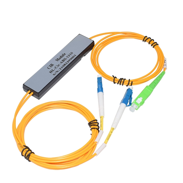
This guide demystifies fiber optic splitters, explaining their design, operating principles, types, key specifications, and real-world applications. Whether you're a network engineer designing a PON (Passive Optical Network) or a homeowner curious about how your fiber connection works. I'm planning to use a TP-Link MC220L transceiver to convert the optical signal to ethernet. This ethernet will then go through a 1 Gbit/s switch, and rout two ethernet cables to each floor. On each floor each ethernet cable will be connected to a router, which will then distribute the internet. DWDM/CWDM is like a two-edged sword. For a small fee (the procurement of the modules and the circulator) you can split/splice one physical fibre optic cable into multiple pairs. The downside is that once you loose your one-and-only fibre link (to a cable-hunting-buck-hoe) then you're in trouble. Fiber optic splitters enable the division of optical signals into multiple paths, allowing information to be distributed to multiple subscribers or devices simultaneously. Understanding the inner workings of fiber optic splitters is crucial for network administrators, technicians, and anyone. The answer is yes, and it's a practice widely used in the industry to distribute signals to multiple destinations without degrading the signal quality significantly. What is Fiber Line.
[PDF]

Insert the end of your fiber optic network line into the fiber optic connector on the converter box. Plug an Ethernet cable into the Ethernet port on the converter box and plug the other end into one of the Ethernet ports on the back of your Ethernet switch. As we speak I just have optic fibre (Community Fibre) connected to my Huawei modem / Linksys Velop which will be connected to a new POE switch (need to identify the best model to be compatible with my optic fibre extension project). The objective is to run 1 or 2 additional optic fibre from the. Connecting a fiber optic switch involves several steps, ensuring compatibility between the switch's ports and the fiber optic cable. Fiber optic switches utilize. Fiber optic cabling is increasingly used to connect network switches and other datacom equipment, especially in long-distance and mission-critical applications. Fiber provides: Increased internet signal bandwidth. Advantages Determine the length of the fiber run and choose either multi mode for runs under 1000 feet or single mode for runs over 1000 feet.
[PDF]
Learn how to safely wire a single-pole (one way) light switch in this beginner-friendly tutorial. Whether you're replacing an old switch or doing your first DIY electrical project, this guide will walk you through every step — no experience needed!. more. This page contains wiring diagrams for household light switches and includes: a switch loop, single-pole switches, light dimmer, and a few choices for wiring an outlet/switch combo device. That's because virtually all light switches that control 120-volt fixtures are single-pole switches. Most light switches are also single-throw, which. Summary: Fully explained wiring diagrams and photos show how to wire switches including: single switches, 3-way switches, 4-way switches, and dimmer switches. and Be Sure to Subscribe! Make sure the circuit power has been turned off, and mark the circuit breaker or fuse to indicate that work is. A distribution board or distribution box is where the main power supply is distributed to multiple loads. And all the switching and protective devices are installed in the distribution box. Single Phase Distribution Box generally consists of Double Pole MCBs, Single Pole MCBs, and RCCBs. Wiring a single light switch may seem like a daunting task, but with the right tools, a bit of patience, and this comprehensive guide, you'll be able to tackle this DIY project with confidence. Remember, while this guide provides detailed instructions, always prioritize safety and consult a.
[PDF]

Materials $450, labor $900, permits $0–$200, total $1,350–$1,550, per-breaker costs vary, overall project time 4–6 hours. Span reflects standard new breakers and enclosure. Mid-Range: 150–200A upgrade, some rerouting, outdoor panel, weatherproof box. Buyers typically pay a broad range for replacing a distribution box, driven by box size, amperage, wiring runs, and local labor rates. This article outlines the cost factors, price ranges, and practical budgeting advice for a U. Key cost drivers include panel amperage, indoor vs outdoor location, wiring length, and whether a full panel upgrade or rerouting is needed. The article outlines cost ranges, per-unit pricing, and practical. If you're planning a new commercial building or upgrading an existing space, our commercial electrical installation calculator can help you estimate what your project might cost. The average cost to hire an electrician to install or repair light fixtures, outlets, switches, or fans ranges from $141 to $419 with homeowners spending $280 on average. For larger electrical jobs like installing wiring or replacing an electrical panel, expect to pay $2,000 to $6,000.
[PDF]
Fiber optic switches are devices used to control the flow of light in fiber optic networks. They are used in a wide range of applications, including telecommunications, data centers, industrial automation, and military and aerospace. This piece analyzes how these switches can make a difference today. Fiber optic switches offer numerous advantages over traditional. A fiber optic switch is an electronic device that allows multiple fiber optic cables to be connected and selectively route data between them. The switch receives data packets from one input fiber optic cable and forwards them to the appropriate output cable based on their destination addresses. It operates on the same principle as an electrical switch, but instead of using electrical signals, it uses light signals to switch data packets from one fiber optic cable to another. Fiber. A fiber optical switch, also known as a fiber channel switch or a SAN (Storage Area Network) switch, is a high-speed network transmission relay device. This technology offers significant.
[PDF]

Use two fibers: one dedicated to TX, the other to RX. Both sides transmit and receive at the same wavelength (common values: 850 nm MM, 1310 nm/1550 nm SM). The front panel is usually labeled TX and RX, and you cross-connect TX→RX, RX→TX with a duplex patch cord. Switch optical port intercommunication means that the optical fiber ports of two switches are connected to each other to achieve the purpose of network connection. The connection between two or more Ethernet switches in a certain way (Uplink port, etc. ) is called the cascade. SFP modules insert into these slots and and require two strands of fiber, typically duplex Using multi mode fiber (for runs under 1000 feet) or duplex single mode fiber (for runs over 1000 feet). This is a cost-effective and high performance way to connect network switches. Use one fiber strand for both. The switch supports 10 Mbps, 100 Mbps, and 1000 Mbps connections. Using Gigabit Ethernet (1000 Mbps), the switch sends files across the network at speeds up of to 2000 Mbps due to the full-duplex nature of Gigabit Ethernet connections. You can either connect 24 Ethernet copper cables or 22 copper. Port types are limited to two: optical and Ethernet. Optical ports on switches typically accommodate optical modules for transmitting data via fiber optic cables. In situations where there's a shortage of Ethernet ports, some users may insert Ethernet port modules into optical ports to connect with.
[PDF]
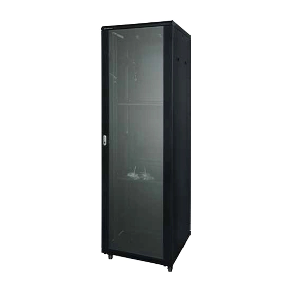
Rack height is measured in rack units (U), where 1U equals 1. Common rack formats include: 24U and below — typical for branch offices or small server rooms. Below is a comprehensive, fully detailed guide covering all standard server rack sizes, form factors, height considerations, depth classifications, and best-practice configuration approaches for professional environments. What Is a Server Rack? Understanding the Core Structure A server rack is a. This comprehensive blog post demystifies the "U" unit in network server accessories—the standard measurement that defines the height of equipment in server racks. A 2U server occupies two rack units, while a 4U server takes up four. Each rack is equipped with mounting rails. A “Rack Unit” (U) is a standard height measure for mounting equipment in a server rack. This article explains definition, planning, installation tips, and trends. At Secure Gates Inc., we provide high-quality 6U, 9U, and 12U Network Rack Cabinets designed to meet the unique needs of professionals, businesses, and data centers. In this blog post, we'll explore what network rack cabinets are, their key benefits, and help you decide which size— 6U, 9U, or 12U. U (rack unit, RU) is a unit of equipment height in a 19" rack. Important: U describes height only, but a server's real "capabilities" are also determined by chassis depth, internal layout, airflow, rails, power, and expansion (PCIe/risers, NVMe.
[PDF]
You can connect two Switch consoles via a network in two ways: Wi-Fi or Ethernet cable. For a more stable wired connection, use a Nintendo Ethernet adapter and a category 5e or higher cable. Important: A USB LAN Adapter can be connected to Nintendo Switch Lite using a licensed accessory, such as the Dual USB PlayStand for Nintendo Switch Lite from HORI. Nintendo Switch can connect online with a wireless connection or, when through use of a LAN adapter, a wired connection. Game sharing between two Switch consoles involves setting up your Nintendo. TL;DR: Is there a way to have two different (unreliable) ISPs connected to a single network switch, so that when one drops out, the home network is automatically switched to the other ISP? --- Hi all! I am a networking hobbyist, and I built out a home network for a family friend of mine living in. To view and connect your Nintendo Switch to either the 2. 4 GHz or 5 GHz Wi-Fi band, follow these steps:. 4 GHz and 5 GHz. But before we get into the details, it's essential to understand that the Nintendo Switch supports both 2. 4GHz and 5GHz WiFi frequencies, ensuring faster and more reliable connectivity. Cisco ® Catalyst ® 9200 Series switches extend the power of intent-based networking and Catalyst 9000 hardware and software innovation to a broader set of deployments. With its family pedigree, Catalyst 9200 Series switches offer simplicity without compromise – it is secure, always on, and IT.
[PDF]

Are the protection parameters set correctly (trip value, trip time)? Is the assigned protection function blocked? Is the protection function´s trip signal routed to the Trip-Manager of the correct switchgear? Is the trip signal of the switchgear . Are the protection parameters set correctly (trip value, trip time)? Is the assigned protection function blocked? Is the protection function´s trip signal routed to the Trip-Manager of the correct switchgear? Is the trip signal of the switchgear . Master trip relay or lockout relay, also known by ANSI code 86, holds a significant position as an intermediator between the protection relay and control points, even though it is not self-equipped with fault sensing capabilities. The master trip relay can operate as a hub of multiple protection. Since protection relays can be expensive, it is not advisable to connect them directly to the trip coil. if the fault detected by any of the protection relay means at the same time the protection relay trips the associated circuit breaker through the mater tripping relay circuits. Master trip relay is not a monitoring relay. It. After first start-up of the protective device there is a pending trip. Two red LEDs are illuminated at the front of the HMI. It typically refers to the time duration taken a.
[PDF]