
In the 2020 NEC ®, no more than 18 inches of cable length is allowed between the cable entry to the box and the closest cable support (see image). Below is a preview of the NEC®. ORG for the complete code section. The previous code language could technically allow an unlimited length of coiled up NM cable inside the wall as long as it was secured within 12 inches of the box. This code is based upon the type of box, wires, wire sizes, wire clamps and conduit fittings. Adjustments are made for the ground wire as you will see in the. Calculate and select the right number and spacing of cables for junction boxes using NEC guidelines to ensure safe, code-compliant electrical installations. This step keeps your project safe and. According to the National Electrical Code (NEC), the conductor must be long enough to extend outside the box's opening. This length allows enough room to connect, splice, or terminate wires without strain or damage. If wires are too short, they may fail inspection or create hazards during. The length of wire left inside an electrical box is a matter of strict compliance, safety, and functionality. Having the correct amount of slack ensures that future maintenance, repairs, or device replacements can be performed without difficulty. Proper electrical box fill calculations are critical for code compliance and safety in both residential and commercial installations.
[PDF]

Average Optical Power: How bright the light is (measured in dBm). Too dim? Your signal gets lost in the fiber. Extinction Ratio: The difference between “on” (1) and “off” (0) light power. A higher ratio = cleaner signals. Transmitter Side: An electrical signal hits a laser diode (LD) or LED, which spits out light. Receiver Side: Light enters a photodetector (like a tiny solar cell), which turns it back into electricity. A built-in amplifier boosts the signal for your. The average transmitted optical power refers to the optical power output by the light source at the transmitting end of the optical module under normal working conditions, which can be understood as the intensity of light. In communication, we usually use dBm to represent optical power. However, in practical use, we adopt the average Tx power. The transmission power is related to the. This article provides an in-depth analysis of two key performance indicators of optical modules: transmitter power and receiver sensitivity. Transmitter power characterizes the average optical power output from the laser under rated conditions, while receiver sensitivity indicates the minimum. An optical module is a connecting module that serves as an optical-electrical conversion device. At the receiver end, the optical signals are reconverted into electrical.
[PDF]

Non-polarizing beamsplitters are specified by their splitting ratio, i. the ratio of P-polarized light to. A beam splitter or beamsplitter is an optical device that splits a beam of light into a transmitted and a reflected beam. It is a crucial part of many optical experimental and measurement systems, such as interferometers, also finding widespread application in fibre optic telecommunications. a laser beam) into two (or sometimes more) beams, which may or may not have the same optical power (radiant flux). Different types of beam splitters exist, as described in the. The collimated incident laser beam passes through the beam splitter, and the output beam is emitted at a specific separation angle on the output beam array. The following figure is an introduction to the basic settings of a beam splitter. Circular beamsplitters, plate beamsplitters and cube beamsplitters can be purchased for polarizing or non polarizing beamsplitting. Beamsplitters are optical components used to split incident light at a designated ratio into two separate beams.
[PDF]

The typical setup time for a standard rapid deployment telecom tower ranges from 15 to 60 minutes once the unit arrives on site. However, complex installations requiring guy wires, heavy payloads, or difficult terrain can extend this window to 2-4 hours. How Should You Prepare for Installing Fiber Optic Internet? Before installing fiber optic internet, ensure your business location is ready. Site Planning and Design: This phase involves assessing the need for a new mobile site, selecting a suitable location, and designing the layout of the infrastructure. Conduct radio frequency (RF) planning and coverage analysis to determine areas with poor or no signal. Analyze user demand and. Equipment installation: Once the site is prepared, the equipment can be installed. This includes installing the telecom equipment in the cabinets, setting up the antennas, and running the cables. Testing and commissioning: Once the equipment is installed, it needs to be tested and commissioned to. Assuming the design is completed, we're looking at the process of physically installing and completing the network, turning the design into an operating system. Since. How long does it take to install fiber optic internet? The time it takes to install fiber optic internet depends on your home's layout and existing infrastructure. Will the technician dig up my yard to install fiber optic internet? Your fiber technician will need to either bury the fiber in your.
[PDF]

To use a power meter for fiber optic testing, always clean connectors first with lint-free wipes or click-to-clean tools. Select the correct wavelength and set your reference. You measure optical power in dBm or insertion loss in dB. Consistent procedures ensure accuracy. Verify light travels from. The most basic fiber optic measurement is optical power from the end of a fiber. This measurement is the basis for loss measurements as well as the power from a source or presented at a receiver. Typically both transmitters and receivers have receptacles for fiber optic connectors, so measuring the. An optical power meter measures the strength of light traveling through a fiber optic cable, giving you a reading in dBm (decibels relative to one milliwatt). This article will guide you through the methods, instruments, and key considerations for measuring fiber. Fiber optic cabling is the high-performance core of today's datacom networks. As network speeds and bandwidth demands increase, fiber performance requirements have become more stringent. Fiber testing is more important than ever. An OPM uses a photodiode to generate an electrical current proportional to optical power.
[PDF]

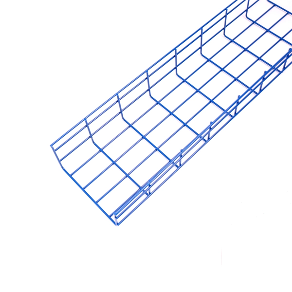
Cable tray support quantity can be calculated using a simple formula: Support Quantity = Total Length ÷ Support Spacing + 1 20 ÷ 2 + 1 = 11 supports In a typical project, a 20-meter cable tray with 2-meter spacing requires 11 supports. Calculating the cable tray support quantity is a crucial part of electrical installation projects. In complex engineering environments, the. Properly sizing your cable tray is critical for safety and compliance. Our free calculator helps you determine the correct tray size based on NEC and IEC standards. This calculator features an interactive interface with advanced visualizations. Open the full calculator for the best experience. Save your cable tray sizing calculator results as branded PDF. Calculate NEC-compliant wire basket cable tray fill, load capacity, and hardware requirements for professional installations. We independently provide precision steel tools, calculators, and expert resources for steel, metalworking, construction, and industrial projects. IEC 61537 covers cable tray and cable ladder systems for the support and accommodation of cables, while NEC Article 392 governs cable. What is the fill capacity and remaining capacity of my cable tray? Calculate cable tray sizing and fill capacity based on tray dimensions, cable diameter, number of cables, and maximum fill percentage per electrical code. Determine whether cables fit within safe fill limits. Cable tray fill.
[PDF]

The first thing you should do is locate the fiber optic cable that comes from the service provider. Once inserted, make sure it is. However, setting up a fiber optic connection to your router can seem daunting if you're unfamiliar with the process. This comprehensive guide combines industry standards with field-tested practices to ensure you achieve a rock-solid. Setting up a fiber internet connection requires understanding key hardware components and following a specific connection sequence to establish your home network. This guide details the necessary physical and digital steps to connect your fiber line and activate your internet service. The technician powers, tests, and activates the connection to confirm full speed and signal quality. * In some instances, the ONT and the router are all in the same device, generally called a combo unit. Here's a step-by-step guide to help you through it. Understand the Basics Before diving in, familiarize yourself with the components involved:. Tecnobits - Router - How to connect a fiber optic cable to the router Hello, Tecnobits! 👋 Connecting fiber optic cables to the router so that your internet flies like a spaceship! 😉 Explore with us on our website! And don't miss our latest news. See you soon! 🚀 How to connect a fiber optic.
[PDF]
Encuentra opciones de almacenamiento y organización en Gabinetes, Racks Servidores y Sistemas de Cableado Estructurado para Redes de Voz y Datos de calidad. Optimiza tu red en Costa Rica. DURABLE - Crafted from cold-rolled steel with a protective black powder coating, the 6U NavePoint Performance Series network cabinet provides sturdy, reliable housing for network and server equipment. Capable of supporting up to 130 lbs, it's an ideal, durable solution for installers working on. TecnoBonilla. com es la mejor fuente para Rack Servers en Costa Rica. Para más información, póngase en contacto con nosotros en 6286-7654.
[PDF]
LC Connectors: Press the latch mechanism and gently pull the connector out. This guide outlines proper methods to safely remove fiber optic cable from modems in your home or office. As an experienced technology writer who has covered broadband advancements for over a decade, I aim to provide readers with trustworthy instructions endorsed by industry experts. Having. Unplugging a fiber optic cable from a modem is a task that requires careful handling to avoid damaging the delicate fibers within the cable. Fiber optic cables are different from traditional copper cables, as they use light to transmit data, and the connectors are more sensitive. This is a popular video tutorial that is often requested by viewers. Fiber optic cables are delicate and require specific handling procedures to maintain their performance and longevity. Is this something that requires a Verizon support tech or can I do it? If so is it as simple as disconnecting and reconnecting or would I have to call support to "reinitiate" my setup. Not my pic, but didn't feel like moving the. Unicom's Wireless Router is a multi-function device providing the following services: • Shared Broadband Internet Access for all LAN users. Page 5 All manuals and user guides at all-guides. com • Virtual Servers. This feature allows Internet users to access Internet servers on your LAN.
[PDF]

Run the display transceiver [ interface interface-type interface-number | slot slot-id ] [ verbose ] command to view information about the optical module on a specified interface. In optical communication equipment, an optical module (Optical Module) contains several types of semiconductor chips that work together to complete the transmission and processing of optical signals. These chips typically include laser chips, photodetector chips, driver chips, transimpedance. When the optical module on an interface is faulty, you can run the display commands to view information about the optical module. Today, we will deeply analyze the four mainstream models of 100G QSFP28 dual-fiber optical modules: QSFP28-100G-SR4, QSFP28-100G-LR4, QSFP28-100G-ER4 and. The following uses the Moduletek SFP-10G-LR module connected to a Huawei S6700 switch as an example to introduce how to read information of the connected optical module on a Huawei switch. Figure 1 Schematic Diagram of Optical Module Connected to Switch 1. Optical Module Status Check Run the. Upgrade to 100G or 400G optics and save. Cisco Transceiver Modules - Learn product details such as features and benefits, as well as hardware and software specifications. Network administrators have a major challenge determining the right Cisco SFP modules, understanding complex model numbers that directly affect network performance and stability.
[PDF]

This guide delves into the structure and working principle of fiber optic connectors and outlines the critical steps for creating a successful connection. There are many types of fiber optic connectors, including SC, LC, FC, ST, D4, MU, MT/MPO, etc. These connectors can be divided into single-mode and multi-mode fiber optic connectors according to their structure and purpose. To learn more about the types of fiber optic connectors, click here: Types. Proper connection of fiber optic cables is essential to harness these benefits fully, as even minor errors can lead to significant performance issues like signal loss. This article will guide you through the necessary tools, materials, and methods on how to connect fiber optic cables effectively. At the heart of any robust fiber optic network lies a crucial process: Preparing a fiber cable for termination of a connector or splice. Fiber optic connectors play an essential role in the realm of optical communication, enabling seamless connections between fiber optic cables. We terminate fiber optic cable two ways - with connectors that can mate two fibers to create a temporary joint and/or connect the fiber to a piece of network gear or with splices which create a permanent joint between the two fibers. Whether you are installing a new network or repairing an existing one, ensuring a proper connection is crucial for maintaining optimal signal.
[PDF]

Fiber Optic Welding How To Joint Fiber Optic Cablesplicing fiber optic cable,fiber optic splice,fiber optic,fiber optics,fiber splice,how to splice,fibre opt. The optical fiber connection adopts the fusion splicing method. The whole process is similar to the welding of metal wires, and it is generally carried out by electric isolation. At the moment, there are two methods of connection: Thermal welding of optical fibers consists in bringing the ends of the conductor to melting using a fiber optic splicer, and more specifically - located inside the electrodes. The welded ends are then pressed and a weld is formed. The most work is waiting for installers, whose tasks can be divided into several stages: In this part, we will deal with the second stage, i. welding, which is considered to be one of the most difficult parts of installers' work in. Open the stripping tube and wipe the grease on the optical fiber with toilet paper and alcohol cotton. On the welding disc, make the optical fiber precoil first and cut the optical fiber into an appropriate length to facilitate the coil fiber work after welding. Add heat shrink tube. Procedure. Another method is to use the so-called mechanical welding. It uses special parts that are prepared in advance to connect the two ends. Thanks to this, you can connect two ends of the cable with a ready-made splice, without the need to use an optical fiber splicer. While this method may appear to be.
[PDF]
Learn the step-by-step process of customizing complete distribution boxes tailored to your needs. From requirement confirmation to design, production, and testing, find out how to get a reliable, flexible distribution system. These versatile units are like the Swiss Army knives of electrical systems – compact, adaptable, and incredibly efficient. But let's be honest, even the best tools can turn into headaches if we don't install. CSS Flexbox is short for the CSS Flexible Box Layout module. Flexbox is a layout model for arranging items (horizontally or vertically) within a container, in a flexible and responsive way. Distribution box refers to the equipment used in the power distribution. Our comprehensive guide to CSS flexbox layout. This complete guide explains everything about flexbox, focusing on all the different possible properties for the parent element (the flex container) and the child elements (the flex items). It also includes history, demos, patterns, and a browser. Our flexible distribution boxes enable reliable, decentralised signal transmission and power transmission up to protection class IP67 – wherever passive distribution boxes are required. From power and signal distribution to I&C applications and complete room solutions - we have just what you need. Our solutions enable short planning and realization times and allow optimized.
[PDF]

While optical power meters are the primary power measurement instrument, optical loss test sets (OLTSs) and optical time domain reflectometers (OTDRs) also measure power in testing loss. TIA standard test FOTP-95 covers the measurement of optical power. This measurement is the basis for loss measurements as well as the power from a source or presented at a receiver. Typically both transmitters and receivers have receptacles for fiber optic connectors, so measuring the. You need a power meter to measure power in a fiber optic system; most power meters come with a screw-on-adapter that matches the connector being tested and a little aid from the network electronics to turn on the transmitter. During the measurement of power, the meter must be set to the proper. Fluke Networks sets the standard in network testing with its advanced range of fiber optic power meters and fault locators, designed to ensure the highest precision in fiber optic meter readings and power evaluations. This is measured in decibels (dB). Splitters, fusion splices, connectors and. To use a power meter for fiber optic testing, always clean connectors first with lint-free wipes or click-to-clean tools. Select the correct wavelength and set your reference. Consistent procedures ensure accuracy.
[PDF]

The first thing you should do is locate the fiber optic cable that comes from the service provider. Once inserted, make sure it is securely. However, setting up a fiber optic connection to your router can seem daunting if you're unfamiliar with the process. Why Use Fiber Optic Internet? Before diving into the setup, let's quickly. Ensure your fiber optic router has an available WAN (Wide Area Network) or Ethernet port for the fiber optic modem. It's thin, flexible, and usually comes with connectors on both ends. Power Cables: Get power cables for both the. The fiber optic cable does not plug directly into a standard home router because the signal type must be translated. The fiber line terminates at the Optical Network Terminal (ONT), which is typically supplied and installed by the internet service provider. This specialized equipment serves as the. The process to connect fiber optic cable to router requires careful attention to detail, but I'll walk you through every critical step with the precision and clarity you deserve. Here's a step-by-step guide to help you through it. Understand the Basics Before diving in, familiarize yourself with the components involved:. Follow along as we take you through the step-by-step process of installing fiber internet! From preparing the site to connecting the final cables, we'll show you what goes into bringing high-speed internet to your doorstep. Whether you're a tech enthusiast or just curious about how it all w.
[PDF]
