This guide will walk you through the process of checking photo sensors using a multimeter, covering various types of photo sensors, the necessary tools and safety precautions, and the specific measurement techniques involved. Knowing how to effectively use a multimeter to test photo sensors can save you time, money, and frustration when dealing with malfunctioning devices. more What is a Voltage Divider? | What is a Voltage. Before replacing the sensor or fixture, it's efficient testing it first, With a few tools and a step-by-step process you can find whether your outdoor lighting control system is working as intended or if the problem lies elsewhere. In this complete guide from Lead-Top, a global leader in photocell. In this blog post, we explain step-by-step how to troubleshoot a sensor with a digital multimeter (DMM). Here are the steps: Troubleshooting a sensor measurement failure requires mechanical tools to uncover the protective shields or components so you can reach the sensor in question. Always follow the manufacturer's instructions for the sensor and multimeter. Ensure the sensor is properly connected to the multimeter and. A multimeter is an indispensable diagnostic tool for anyone working with electronics, electrical systems, or indeed, sensors. It's a versatile device capable of measuring voltage, current, and resistance, providing crucial insights into the health and functionality of electrical circuits and.
[PDF]
This is the FOA's Online Guide To Fiber Optics, Fiber Broadband & Premises Cabling. With 19+ years of experience installing fiber-optic cables at over 20,000 locations, we've seen how prices vary based on cable type, project scope, and installation complexity. Fiber-optic cable materials typically cost $1 to $6 per linear foot, depending on fiber count and cable type. Main cost drivers include cable grade (indoor vs outdoor, armoured), distance, and labor for trenching, splicing, and termination. This guide presents ranges in USD and practical price estimates to help. Fiber optic cables are essential components in today's broadband, FTTx, and data center networks. Whether you're planning a national fiber rollout or sourcing cables for enterprise infrastructure, understanding how fiber optic cable pricing works can help you budget more effectively and make better. We have included Per Foot conversions for reference (1 Meter ≈ 3. Best For. * Disclaimer: Prices fluctuate based on raw material indices (Glass/Copper/Polymer) and cable core count (e. These cables, constructed with glass or plastic fibers, transmit data through light pulses, offering.
[PDF]

This video demonstrates the process of installing a fiber optic sensor to a substrate for measuring distributed mechanical strain. The presenter explains the steps involved in preparing the surface, bonding the sensor, and applying adhesive. Fiber optic sensing (FOS) systems can provide high-fidelity distributed strain measurements in various industries such as aerospace, automotive, structural health monitoring, and civil engineering. Proper fiber optic sensor installation is crucial to obtain accurate and useful strain measurements. Trying to connect your FU Series fiber optic sensor head to the FS-N40 Series fiber optic sen. more Learn more via the catalog: https://www. It is divided into communication supplies and industrial supplies, here we refer to the industrial fiber optic sensor. The presenter explains the. Optical fiber couplers for various LEDs and light sensors are commercially available, but you can skip the connector and simply connect silica and plastic fibers directly to LEDs and sensors. For the examples described here, I used LEDs encapsulated in standard 5mm clear epoxy packages, and. This Application Note is intended to guide users of Luna's High Definition Fiber Optic Sensing (HD-FOS) system (the ODiSI) through the simple process of mounting a fiber sensor onto the surface of a test article.
[PDF]

The fastest way to test a fluorescent tube is with a multimeter set to continuity mode. Each end of the tube has two pins connected by a thin filament inside the glass. If either filament is broken, the tube is dead. The whole test takes about 30 seconds per tube once you know what. This is a complete guide for testing a fluorescent light bulb with a multimeter. You don't have to be an expert in electrical work. This process measures electrical resistance to determine if the tube has suffered an internal failure before replacing the bulb or investigating the ballast. This guide provides a comprehensive understanding of the process, equipping you with the knowledge and. To test a fluorescent light bulb, observe any of the following: flickering light, low brightness, buzzing sound, delayed start, and fading color and light variation. Turn off the power to the circuit that powers the fixture and keep the leads steady to ensure accurate readings. Multimeters provide. How to Test Light Bulbs & Fluorescent Tubes with a Multimeter (Continuity Check) Is your lamp or fixture failing to light up? Before you buy a new bulb, you need to confirm if the bulb or tube itself is the problem! A simple continuity check using a multimeter can instantly tell you if the filament.
[PDF]

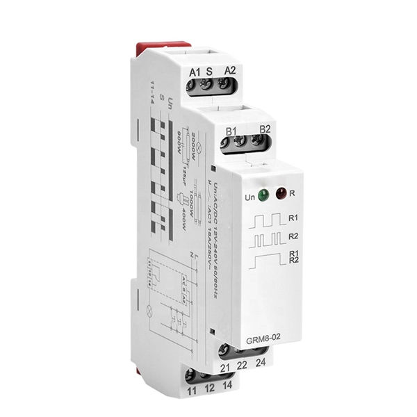
A wiring diagram for a photocell and timeclock controller provides a step-by-step guide for installing and connecting all the components in a light system. It shows exactly how each component fits into the overall scheme of things, as well as what wires to use and which connections to. Intelligent Lighting Controls' wiring diagrams show detailed schematics of our solutions. A lighting control module is the “control center” for your lighting system. It acts as a bridge between your physical lighting fixtures and the smart systems that manage them. Instead of relying solely on traditional wall switches, you can control your lights via remotes, mobile or web apps. This guide will discuss the steps needed to integrate with URC Total Control. Commission CSI Controllers Step 2. Locate/Download latest TCM files/Module Step 3. Network Setup Step 6. Supports DALI V2 compatible switches and sensors, works out of the box. Simple and easy setup. ControlByWeb® IoT controllers are a great fit for lighting control in edge applications. Understanding the components that make up a modern lighting system, and how they relate to one another is key to ensuring the best performance and.
[PDF]

The core measurement procedure follows five steps: Turn on the meter and let it warm up. Most meters need a brief stabilization period before readings are reliable. Check your model's manual, but a minute or two is typical. Set the wavelength to match your light source. Fiber loss is the difference between the power when light is coupled from the transmitting end to the fiber and the power when the light reaches the receiving end. Generally speaking, when measuring the. An optical power meter measures the strength of light traveling through a fiber optic cable, giving you a reading in dBm (decibels relative to one milliwatt). The basic process is straightforward: turn the meter on, set it to the correct wavelength, clean your connectors, plug in, and read the. A power meter and light source are essential test tools that work in tandem to measure fiber optic cable loss and evaluate the quality of optical links. They provide the data necessary to quantify signal loss and pinpoint issues that could impact network performance. Here's how they work: A power. You measure optical power in dBm or insertion loss in dB. Verify light travels from transmitter to receiver. We'll give you the basic information you need and provide some printable references.
[PDF]
Step-by-step instructions on how to install fiber optic connectors like LC, SC, and ST. Includes tool recommendations, epoxy and polish method, and safety tips for installers and technicians. Even with sharing in efficiency, fiber connector installation is still an effort in which precision and safety form the central themes. A correct installation creates a low-loss, reliable connection essential for high-speed data transmission. While fiber optics enable speeds and distances copper can't match, the system's performance hinges. Next, we will introduce in detail the installation of several different types of fiber optic connectors. How To Connect Fiber Optic Cable To Connector? The connection methods for SC, FC, ST, and FT connectors with optical fibers are basically the same. Unlike foil strain gauges, fiber is often suitable for embedment. Sensuron's FOS offers hundreds to thousands of sensing points with a resolution of 1. 4 mm along a single sensing fiber. This video demonstrates the process of installing a fiber optic sensor to a substrate for measuring distributed mechanical strain. Fiber optic connectors are devices that join two fiber optic cables together, allowing the transmission of light signals with minimal loss. They come in various types, such as SC, LC, ST.
[PDF]
Fixed fiber optic attenuators are used to reduce the optical power signal in communication links. They work analogous to a step-down transformer. As the signal approaches a device or node in a communication link the power is reduced to a level that is suitable for its application. They are used to control the power level of optical signals at the outputs of light sources and electrical-to-optical (E/O) converters. Measured in decibels (dB), loss degrades signal quality, limits distance, increases bit-error rate, and escalates infrastructure cost. Understanding and managing it is critical to. The Fiber optic attenuator is an optical device that reduces the energy of the optical signal—used to attenuate the input optical power to avoid the distortion of the optical receiver due to the input optical power being too strong. It works by dissipating a portion of the optical power passing through it, thereby lowering the overall power level. Fiber optic attenuators.
[PDF]
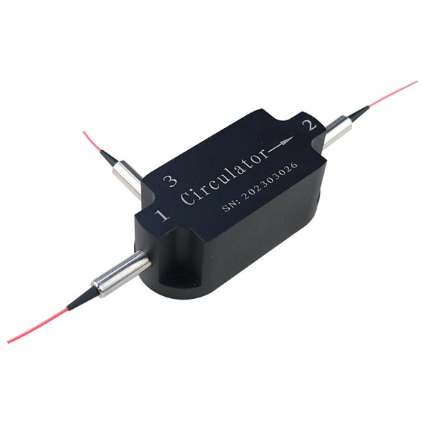
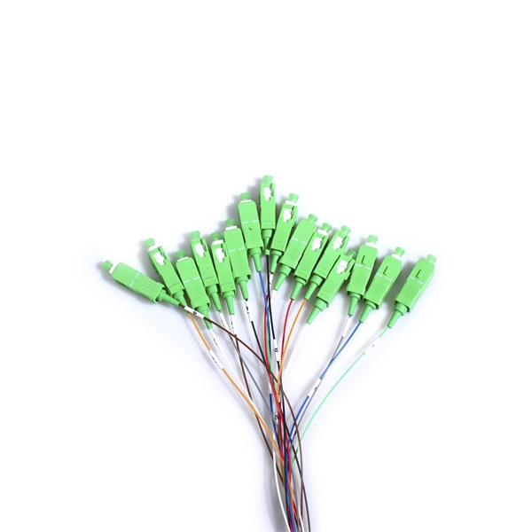
This article explores the different types of Fiber Optic Sensors, their working principles, and various applications. while constructing a complete Fiber Optic Link (Central Office to Outside Plant to Customer Premise). Hence, this course will. The fiber optic sensor has an optical fiber connected to a light source to allow for detection in tight spaces or where a small profile is beneficial. The optical fiber consists of the core and the cladding, which have different refractive indexes. This is a very interesting and also well-known topic in the research field. Fiber optic sensors play a key role in developing the communication system to sense & measure the change within. Imagine a world where the Internet doesn't just connect but senses —detecting earthquakes, monitoring battery health, or safeguarding critical infrastructure. This is the power of fiber optic sensing, a technology that transforms ordinary optical fibers into the digital world's sensory network. We'll delve into Intrinsic, Extrinsic, and Hybrid fiber optic sensors, explaining how they function. A sensor is a device that measures a physical quantity and converts it into a. Konnexx is an industry leader in Jamaica and the Caribbean, providing world class services in the telecommunication and broadband industries offering a wide range of telecommunication support services for commercial and private entities. We offer comprehensive solution for businesses interested in.
[PDF]

This guide discusses common cable tray problems, from loosening and corrosion to grounding issues and installation errors, along with strategies for prevention and resolution. Understanding the root causes of cable tray failures is the first step toward ensuring system reliability. Let's delve into. How far apart should cable trays be supported? What's the risk if support spacing is too wide? Can I reconfigure tray layouts later? What's the best tray material for outdoor use? How can I reduce electromagnetic interference in trays? What are the common faults in cable? What is the most common. The products can be widely used in construction, energy, power, plant. There are five common ways to fix the cover plate of cable tray elbow supplier: pressing plate fixing, screwing fastening, clasping fixing, padlock fixing and seven-shaped buckle fixing. I would like to introduce to you the five. Steel cable trays form the backbone of organized and efficient electrical wiring in industrial, commercial and infrastructure projects. Whether installed as stainless steel cable trays, these components offer durable and flexible solutions for routing cables safely. However, like any other infrastructure, cable trays are prone to failures that can result in serious safety hazards, financial losses, and downtime. The specific operations are as.
[PDF]
00 Original price was: $285. Add an LC fiber optic connection to your Blackmagic Studio Camera, Teranex Converter, ATEM hardware, or any other professional device that supports SFP cages with. Help others learn more about this product by uploading a video! Looking for specific info? Would you like to tell us about a lower price? Found a lower price? Let us know. Although we can't match every price reported, we'll use your feedback to ensure that our prices remain competitive. 6G data rates support SD, HD, and 4K resolutions, and the fiber optic communication allows. FiberMall SFP+ Transceivers are hot swapping, cost effective modules supporting data rate of 6Gbps/8Gbps/10Gbps/16Gbps/32Gbps and up to 120km transmission. Learn more Spread the cost of your purchases over 3 to 24 months with an interest rate from 0. There's no fees if you pay on time. All set! You can manage payments in the Klarna app or website Down payment may be required. Klarna Monthly.
[PDF]
In most cases, you just need to enter the router's IP address into a web browser and then log in with the default admin username and password. For some routers, you can log in with a mobile app. To set up your wireless network, begin by signing in to your GFiber account and navigating to your router's device configuration. Find your appointment using your order ID or internet account number. Check your bill, set up AutoPay, or make a payment. Get AutoPay Select one of our internet-related topics to troubleshoot the issue. We'll. Forgot email? Not your computer? Use a private browsing window to sign in. Learn more about using Guest mode. Ensure you have an active connection (wired or wireless) between the router and the device you're using to access the admin page. If the Wi-Fi connection has been previously disabled through the admin page, you may not be able to enable it after a Factory Reset is completed. Establish a Wi-Fi or. The default router IP for AT&T is usually either 192. 1, depending on the gateway model. Once you've entered the default ATT router login IP, you'll gain access to the. Whether you got your router from your ISP or purchased it yourself, logging in to your router is simple.
[PDF]

This comprehensive guide will explore the importance and benefits of this integration, provide an understanding of fiber optic cable and Ethernet ports, discuss their compatibility, and offer a step-by-step process for connecting them. Proper connection of fiber optic cables is essential to harness these benefits fully, as even minor errors can lead to significant performance issues like signal loss. This article will guide you through the necessary tools, materials, and methods on how to connect fiber optic cables effectively. Using an optical cable involves connecting it to the right equipment, ensuring proper installation, and testing the system for optimal performance. Here's a step-by-step guide on how to use optical cable effectively: 1. Check Compatibility of Equipment Ensure that your equipment (e., network. One powerful solution to achieve these goals is by connecting fiber optic cables with Ethernet ports. This comprehensive guide combines industry standards with field-tested practices to ensure you achieve a rock-solid. These transceiver modules are hot-swappable input/output (I/O) devices that plug into 100BASE, 1000BASE and 10GBASE ports (for SFP+), which connect the module port with the fiber-optic or copper network. The SFP transceiver modules are hot-pluggable I/O devices that plug into module sockets. The number one cause of signal loss in optical fiber installations is dirt on.
[PDF]

This guide provides a complete framework for understanding, identifying, and planning MPO connector gender in data center environments. Visually, male and female MPO connectors are easy to distinguish: male connectors feature two alignment pins (PIN pins), while female connectors have corresponding holes instead of pins. An MPO connection is made between a male and female connector to make sure that there is proper alignment. Interfaces on active MPO equipment, such as transceivers are usually male, so any MPO trunk cable. In modern data centers and high-density fiber optic networks, MPO (Multi-Fiber Push-On) connectors have become an essential solution for achieving fast, reliable, and scalable connectivity. You will discover the physical distinctions between male and female connectors and how to develop a gender strategy for your infrastructure, which gender connects. Whether you're supporting parallel optics like 100G SR4 or densifying an optical distribution frame (ODF), MPO is now a cornerstone of network design. This article explains: And a practical checklist to design MPO systems that scale cleanly. If you only remember one thing: MPO is a multi-fiber. In MPO and MTP fiber connector systems, Male vs Female and Pin vs No-Pin describe the same core engineering attribute: the presence or absence of alignment pins on the MT ferrule. Unlike single-fiber connectors such as LC or SC, this distinction is not optional terminology but a mandatory.
[PDF]
Just snap the dust cap over the electrical connector or port for which it's designed. This manual details the installation, operation and maintenance instructions for type JBDB Junction/Terminal Box (flameproof). This product is ATEX and IECEx certified to meet the requirements for hazardous location equipment. You don't need any special tools or equipment to install a dust cap. Once installed, the dust. As with most tasks, there are many ways to terminate motor leads and each one has a following who believe it is the best method. Here we will discuss some of these procedures and outline a few of the advantages and disadvantages of each. We will not consider the starting method or inter-nal. An electrical junction box is a protective housing designed to enclose and shield electrical wire connections or splices. For outdoor installations, the box must defend these sensitive splices against moisture, dust, temperature fluctuations, and physical impacts. Using a purpose-built.
[PDF]