
The fastest way to test a fluorescent tube is with a multimeter set to continuity mode. Each end of the tube has two pins connected by a thin filament inside the glass. If either filament is broken, the tube is dead. The whole test takes about 30 seconds per tube once you know what. This is a complete guide for testing a fluorescent light bulb with a multimeter. You don't have to be an expert in electrical work. This process measures electrical resistance to determine if the tube has suffered an internal failure before replacing the bulb or investigating the ballast. This guide provides a comprehensive understanding of the process, equipping you with the knowledge and. To test a fluorescent light bulb, observe any of the following: flickering light, low brightness, buzzing sound, delayed start, and fading color and light variation. Turn off the power to the circuit that powers the fixture and keep the leads steady to ensure accurate readings. Multimeters provide. How to Test Light Bulbs & Fluorescent Tubes with a Multimeter (Continuity Check) Is your lamp or fixture failing to light up? Before you buy a new bulb, you need to confirm if the bulb or tube itself is the problem! A simple continuity check using a multimeter can instantly tell you if the filament.
[PDF]
Fiber testing is the process of verifying the performance of optical fiber cabling. This process includes a range of tests and measurements such as insertion loss, optical return loss, and fiber length. It encompass.
[PDF]

This guide will walk you through the process of checking photo sensors using a multimeter, covering various types of photo sensors, the necessary tools and safety precautions, and the specific measurement techniques involved. Knowing how to effectively use a multimeter to test photo sensors can save you time, money, and frustration when dealing with malfunctioning devices. more What is a Voltage Divider? | What is a Voltage. Before replacing the sensor or fixture, it's efficient testing it first, With a few tools and a step-by-step process you can find whether your outdoor lighting control system is working as intended or if the problem lies elsewhere. In this complete guide from Lead-Top, a global leader in photocell. In this blog post, we explain step-by-step how to troubleshoot a sensor with a digital multimeter (DMM). Here are the steps: Troubleshooting a sensor measurement failure requires mechanical tools to uncover the protective shields or components so you can reach the sensor in question. Always follow the manufacturer's instructions for the sensor and multimeter. Ensure the sensor is properly connected to the multimeter and. A multimeter is an indispensable diagnostic tool for anyone working with electronics, electrical systems, or indeed, sensors. It's a versatile device capable of measuring voltage, current, and resistance, providing crucial insights into the health and functionality of electrical circuits and.
[PDF]
A solar meter, also known as a solar irradiance meter or pyranometer, is a device that measures the amount of solar energy or irradiance emitted by the sun. It is commonly used in solar power applications to op.
[PDF]
Den här guiden går igenom allt du behöver känna till när du vill koppla din egen router till fiber, vilka alternativ som finns, vilka inställningar som krävs och hur du felsöker om något inte fungerar som det ska. However, setting up a fiber optic connection to your router can seem daunting if you're unfamiliar with the process. In this guide, we'll walk you through how to connect a fiber optic cable to a router safely and efficiently. Why Use Fiber Optic Internet? Before diving into the setup, let's quickly. Setting up a fiber internet connection requires understanding key hardware components and following a specific connection sequence to establish your home network. This comprehensive guide combines industry standards with field-tested practices to ensure you achieve a rock-solid.
[PDF]
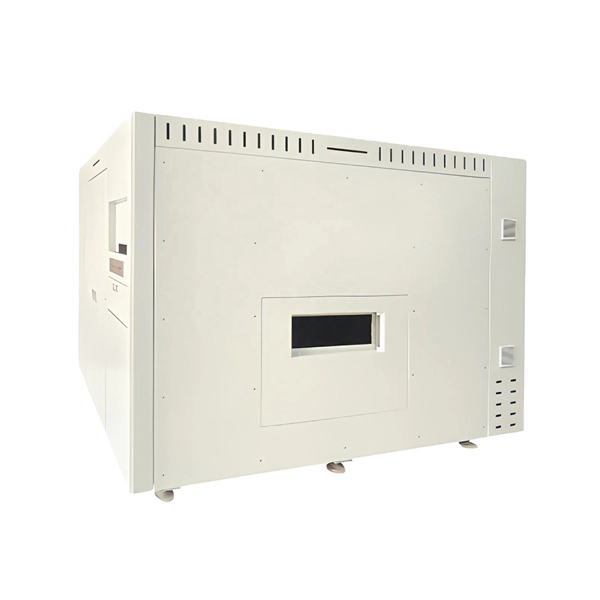
Learn the step-by-step process of customizing complete distribution boxes tailored to your needs. From requirement confirmation to design, production, and testing, find out how to get a reliable, flexible distribution system. These versatile units are like the Swiss Army knives of electrical systems – compact, adaptable, and incredibly efficient. But let's be honest, even the best tools can turn into headaches if we don't install. CSS Flexbox is short for the CSS Flexible Box Layout module. Flexbox is a layout model for arranging items (horizontally or vertically) within a container, in a flexible and responsive way. Distribution box refers to the equipment used in the power distribution. Our comprehensive guide to CSS flexbox layout. This complete guide explains everything about flexbox, focusing on all the different possible properties for the parent element (the flex container) and the child elements (the flex items). It also includes history, demos, patterns, and a browser. Our flexible distribution boxes enable reliable, decentralised signal transmission and power transmission up to protection class IP67 – wherever passive distribution boxes are required. From power and signal distribution to I&C applications and complete room solutions - we have just what you need. Our solutions enable short planning and realization times and allow optimized.
[PDF]
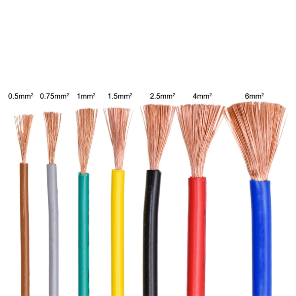
If a steel cable tray costs $5 per meter, the cost per foot would be approximately $1. The average cable tray price per meter ranges from $2 to $25, depending on material, type, size, and surface finish. 👉 For bulk orders or project pricing, the cost can be significantly lower. The main cost driver is the material used in manufacturing: 🔹 Galvanized steel is the most common. Although metal pipes (conduit) may appear cheap initially, they tend to be the most costly option when the job is finally complete, since they consume a lot of time to install. Here is how the three main systems compare when looking at the total bill. Why is Conduit So Expensive? Wires go through a. How can we improve? Choose from our selection of ladder cable trays, including cable and hose trays, heavy duty open cable and hose carriers, and more. Same and Next Day Delivery. Aluminum cable ladders are easy to install and cost less than steel cable ladders. Their lightweight construction makes them easy to work with and transport. This is advantageous because it saves on installation costs and time. Cable trays are vital in electrical installations, providing secure pathways for power, communication, and control cables across residential, commercial, and. Cable ladder trays have side rails with rungs to route and support cable. These trays also provide free air flow to prevent overheating, which could damage the cable. They mount overhead or under.
[PDF]

Get answers to frequently asked questions about broadband services at BTC Bahamas. At Lightcommunication Company, we specialize in comprehensive fiber optic solutions, ensuring superior connectivity through expert services in installation, splicing, and network maintenance. We strive to revolutionize communication by providing cutting-edge fiber optic services that empower. BTC, also known as the Bahamas Telecommunications Company, is the national telecommunications company of the Bahamas. It offers a range of internet services, including fibre optic and DSL connections, and has a wide network of fibre optic cables, allowing it to provide high-speed internet to both. Clear Fiber Technology Solutions is a leading and reputable Telecommunications Contracting and Consulting Firm serving the Bahamas and Caribbean area. We understand the importance of Professional and Reliable Communications Services. We take a comprehensive approach to secure solutions, providing. Our aim is to provide reliable, cost effective, comprehensive solutions with efficient service to assist you in building I. infrastructure you can depend on. We want to be your partner of choice. call on us when you need to build out, upgrade or expand. Along the way we make it our mission to enrich lives and businesses through reliable, fast and future ready technology. Cable Bahamas nurtures education, wellness and cultural growth through dedicated partnerships and.
[PDF]

The typical setup time for a standard rapid deployment telecom tower ranges from 15 to 60 minutes once the unit arrives on site. However, complex installations requiring guy wires, heavy payloads, or difficult terrain can extend this window to 2-4 hours. How Should You Prepare for Installing Fiber Optic Internet? Before installing fiber optic internet, ensure your business location is ready. Site Planning and Design: This phase involves assessing the need for a new mobile site, selecting a suitable location, and designing the layout of the infrastructure. Conduct radio frequency (RF) planning and coverage analysis to determine areas with poor or no signal. Analyze user demand and. Equipment installation: Once the site is prepared, the equipment can be installed. This includes installing the telecom equipment in the cabinets, setting up the antennas, and running the cables. Testing and commissioning: Once the equipment is installed, it needs to be tested and commissioned to. Assuming the design is completed, we're looking at the process of physically installing and completing the network, turning the design into an operating system. Since. How long does it take to install fiber optic internet? The time it takes to install fiber optic internet depends on your home's layout and existing infrastructure. Will the technician dig up my yard to install fiber optic internet? Your fiber technician will need to either bury the fiber in your.
[PDF]

The first thing you should do is locate the fiber optic cable that comes from the service provider. Once inserted, make sure it is securely. However, setting up a fiber optic connection to your router can seem daunting if you're unfamiliar with the process. Why Use Fiber Optic Internet? Before diving into the setup, let's quickly. Ensure your fiber optic router has an available WAN (Wide Area Network) or Ethernet port for the fiber optic modem. It's thin, flexible, and usually comes with connectors on both ends. Power Cables: Get power cables for both the. The fiber optic cable does not plug directly into a standard home router because the signal type must be translated. The fiber line terminates at the Optical Network Terminal (ONT), which is typically supplied and installed by the internet service provider. This specialized equipment serves as the. The process to connect fiber optic cable to router requires careful attention to detail, but I'll walk you through every critical step with the precision and clarity you deserve. Here's a step-by-step guide to help you through it. Understand the Basics Before diving in, familiarize yourself with the components involved:. Follow along as we take you through the step-by-step process of installing fiber internet! From preparing the site to connecting the final cables, we'll show you what goes into bringing high-speed internet to your doorstep. Whether you're a tech enthusiast or just curious about how it all w.
[PDF]

As fiber optic cables are generally only produced in lengths up to around 5 km, so when lengthier connections are needed, splicing two cables together becomes necessary. So in essence, fiber optic splicing is a process used to join two separate fiber optic cables together. There are numerous use cases for fiber optic splicing. As. The time it takes to splice a fiber optic cable can vary depending on several factors, including the type of splice, the equipment used, and the level of expertise of the technician performing the splice. Proper termination is essential for ensuring optimal performance, reducing signal loss, and maintaining the durability of the connection. Another method of connecting optical fibers is termination or connectorization, which consists of processing the end of a fiber optic bundle so that it can be connected to other fibers or devices through fiber optic. Fiber optic joints or terminations are made two ways: 1) splices which create a permanent joint between the two fibers or 2) connectors that mate two fibers to create a temporary joint and/or connect the fiber to a piece of network gear. Either joining method must have three primary characteristics.
[PDF]

In this tutorial, I will show you how you can connect the Optocoupler to Arduino, read the data as Analog or Digital, and if necessary convert the analog values to digital, and how to reduce noise from the sensor. The Infrared Slotted Optical Optocoupler Module is a device that uses infrared light to transmit signals between two electrically isolated circuits. It consists of an infrared emitter (LED) and a photodetector (phototransistor) housed in a slotted enclosure. When an object passes through the slot. Slotted Optocouplers (Photo Interrupters) are very useful sensors, often included in Arduino projects to detect position of moving objects, measure speed of rotation, or linear motion, frequency of events, and many others. They are easy to use, but it is important to understand how they work, so. This tutorial is a comprehensive, practical guide to the Speed Sensor / Tacho Sensor (Slot-Type Optocoupler) (Leobot Product #245). Moreover, a simple application is programmed that shows how to wire and how to program an Arduino when working with the module. In this tutorial, the module is used as an “digital input board”. If you want to use the. In this project, I will talk about Phototransistor Optical Interrupter Switches (Opto Coupler) Module, how this module works and helps in determining the speed of a rotating object and finally I will show you how to Interface Optical Interrupter Switch Sensor with Arduino and measure the speed of a.
[PDF]
This guide dives deep into the most prevalent fiber optic network problems, their root causes, and actionable solutions. Fiber optic technology is essential for modern communication, offering unparalleled speed, reliability, and efficiency. However, improper installation can lead to severe performance issues, expensive repairs, and unnecessary downtime. To ensure a high-functioning fiber optic network, avoid these. Understanding the common causes of failure and implementing preventive measures is essential to maintaining reliable networks and avoiding costly downtime. In this article, we explore the primary modes of field failure in fiber optic cables and outline best practices to prevent them. This article outlines three key errors and how to avoid them.
[PDF]

This is a simple video showing how to install a 850nm fiber optic link using SFP transceivers between 2 10 Gigabit backbone switches. Covers transceiver inst. As a leading provider of fiber optic solutions, Weunion offers a wide range of SFP-compatible products, including optical transceivers, DAC/AOC cables, LC patch cords, and MPO/MTP assemblies. This guide explores the essentials of SFP connectivity, installation best practices, and how Weunion's. These transceiver modules are hot-swappable input/output (I/O) devices that plug into 100BASE, 1000BASE and 10GBASE ports (for SFP+), which connect the module port with the fiber-optic or copper network. This document contains these sections: The SFP transceiver modules are hot-pluggable I/O. An optical module is an optoelectronic conversion device that transmits data by converting electrical signals into optical signals. Common types of optical modules include SFP, SFP+, SFP28, QSFP, QSFP28, etc. Different types of optical modules have different performance parameters such as speed. The 1310 nm WWDM solution, 10GBASE-LX4, requires the use of a mode-conditioning patch cord on multimode fiber to achieve its specified range of operating distances. more Audio tracks for some languages were automatically generated. Learn more This is a simple. One of the most widely deployed optical solutions for short-distance 10G links is the multimode SFP+ transceiver, commonly referred to as a 10GBASE-SR module.
[PDF]
We're talking anywhere from $45 for a small residential unit to over $6,000 for industrial-grade modules. In this guide, as a professional hollow fiber membrane manufacturer, I'll break down exactly what influences these prices and how to get the best value for your specific. What's the hollow fiber membrane price going to set you back? Here's the deal: Hollow fiber membrane costs vary WILDLY. The Global Hollow Core Fiber Market will grow at a CAGR of 10. 92% from 2025 to 2031, reaching USD 24. Industrial uses and innovation fuel this surge, with the market predicted at USD 11. The pricing dynamics of the hollow core fiber market are influenced by factors. Check each product page for other buying options. Price and other details may vary based on product size and color. Need help?. The price of hollow fibers varies significantly based on material composition, manufacturing process, sustainability, and performance characteristics. Understanding the different types helps buyers make informed decisions for both commercial and personal applications. Fibers colored during the. Cobetter hollow fiber filters are made of low-binding modified polyethersulfone membranes (m-PES) that deliver excellent filtration performance. The low shear stress makes it ideal for the processes of cell harvest, clarification, diafiltration and concentration where gentle and fast separation is.
[PDF]


