
The fastest way to test a fluorescent tube is with a multimeter set to continuity mode. Each end of the tube has two pins connected by a thin filament inside the glass. If either filament is broken, the tube is dead. The whole test takes about 30 seconds per tube once you know what. This is a complete guide for testing a fluorescent light bulb with a multimeter. You don't have to be an expert in electrical work. This process measures electrical resistance to determine if the tube has suffered an internal failure before replacing the bulb or investigating the ballast. This guide provides a comprehensive understanding of the process, equipping you with the knowledge and. To test a fluorescent light bulb, observe any of the following: flickering light, low brightness, buzzing sound, delayed start, and fading color and light variation. Turn off the power to the circuit that powers the fixture and keep the leads steady to ensure accurate readings. Multimeters provide. How to Test Light Bulbs & Fluorescent Tubes with a Multimeter (Continuity Check) Is your lamp or fixture failing to light up? Before you buy a new bulb, you need to confirm if the bulb or tube itself is the problem! A simple continuity check using a multimeter can instantly tell you if the filament.
[PDF]

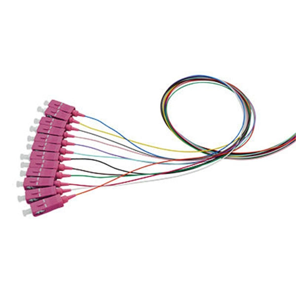
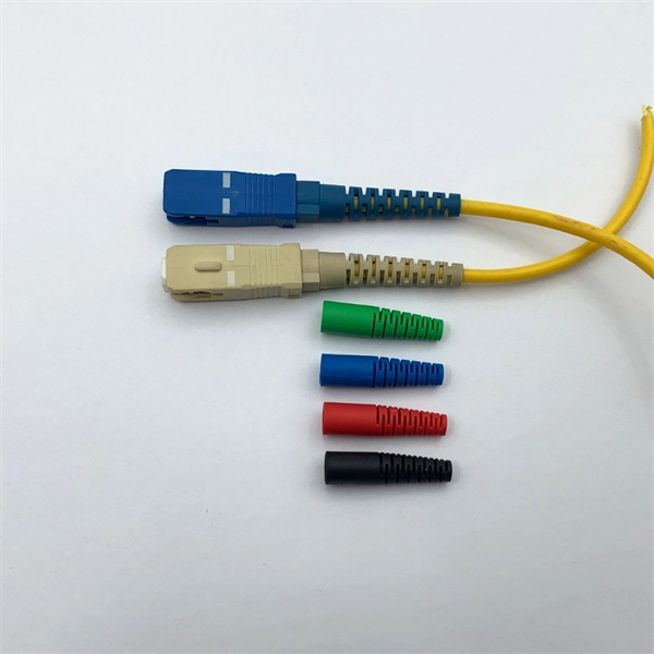
Please view our full RLH price list and contact us at info@fiberopticlink. com if you have any questions or special project needs. A Fiber Optic Patch Panel, also known as an Optical Distribution Frame (ODF) or fiber termination enclosure, is a centralized hardware unit designed to manage, protect, and organize fiber optic cable connections. In an era where data speeds and network reliability are non-negotiable, the patch. fiber optic patch panel, odf, optical distribution frame, fiber distribution panel, rack mount fiber patch panel, wall mount odf, fiber termination box, 1u fiber patch panel, 24 port fiber patch panel, 48 port fiber patch panel, outdoor fiber patch panel, fiber optic odf, sliding patch panel The. Q1: What is the difference between an ODF and a patch panel? An ODF is the entire frame or cabinet managing fiber connections, while a patch panel is a modular unit inside the ODF for cross-connecting fibers. Q2: How many fibers can an ODF handle? It depends on the ODF type; rack-mount units can. ODF is used in the terminal access link of FTTH system. It is a device that splices, distributes, and splits optical fibers and provides protection and management of optical fibers. Belden offers several Fiber Patching Systems. Full patching platforms include FX ECX for LAN environments, FX UHD for high-density fiber channels and the DCX System used primarily in data centers where high amounts of fiber connections and density are the key requirements, as in optical.
[PDF]

This guide will walk you through the process of checking photo sensors using a multimeter, covering various types of photo sensors, the necessary tools and safety precautions, and the specific measurement techniques involved. Knowing how to effectively use a multimeter to test photo sensors can save you time, money, and frustration when dealing with malfunctioning devices. more What is a Voltage Divider? | What is a Voltage. Before replacing the sensor or fixture, it's efficient testing it first, With a few tools and a step-by-step process you can find whether your outdoor lighting control system is working as intended or if the problem lies elsewhere. In this complete guide from Lead-Top, a global leader in photocell. In this blog post, we explain step-by-step how to troubleshoot a sensor with a digital multimeter (DMM). Here are the steps: Troubleshooting a sensor measurement failure requires mechanical tools to uncover the protective shields or components so you can reach the sensor in question. Always follow the manufacturer's instructions for the sensor and multimeter. Ensure the sensor is properly connected to the multimeter and. A multimeter is an indispensable diagnostic tool for anyone working with electronics, electrical systems, or indeed, sensors. It's a versatile device capable of measuring voltage, current, and resistance, providing crucial insights into the health and functionality of electrical circuits and.
[PDF]
A solar meter, also known as a solar irradiance meter or pyranometer, is a device that measures the amount of solar energy or irradiance emitted by the sun. It is commonly used in solar power applications to op.
[PDF]

In this case use an optical power meter (OPM) and test the input port of the splitter for the optical power level (dBm) from the OLT at 1490 nm. If there is no or reduced power then the patchcord or OLT is the culprit. If the power level is reduced it could be as simple as a. So for this simple 1X2 splitter, how do we test it? Simply follow the same directions for a double-ended loss test. Attach a launch reference cable to the test source of the proper wavelength (some splitters are wavelength dependent), calibrate the output of the launch cable with the meter to set. Optical splitters in the outside plant (OSP) are used mostly in passive optical networks (PONs) for fiber-to-the-user (FTTx) networks, and are often overlooked as failure points. In this article I focus on a few basics of optical splitters, their applications, typical causes of failures, and how to. Now, we test the simplest 1x2 optical splitter as the picture shown below. 001 dB), OTDR (for reflection event detection). Cleaning tools. The CertiFiber® Pro Optical Loss Test Set (OLTS) can be used to check that the loss of a PON Splitter (often referred to in various standards as a non-wavelength-selective or wavelength-selective branching device) to check that it is within the allowed defined limits. The CertiFiber® Pro has an.
[PDF]

In this tutorial by TiFi Design, you'll learn in-depth how to create. In this tutorial by TiFi Design, you'll learn in-depth how to create. In this geometry nodes tutorial, learn how to design procedural fiber optics in Blender! You'll learn in-depth how to create, distribute, and reshape splines; capture attributes; and use those attributes to build a vibrant shader. more In this geometry nodes tutorial, learn how to design. Building Information Modeling (BIM) uses multi-dimensional, spatial models that incorporate detailed product information for the building components. Blender enthusiast and YouTuber, I make video. Just wanted to share my recent geometry nodes tutorial on how to design brilliant fiber optics. I hope you enjoy it! https://youtu. be/l-OGJml_sRQ The largest. When communicating between systems, either via the internet or via an internal network system, a medium needs to be in a place that can facilitate the transmission of data, both sending and receiving. There are numerous options available for laying down communication mediums, such as coaxial cable. The Computer-Aided Design ("CAD") files and all associated content posted to this website are created, uploaded, managed and owned by third-party users. Each CAD and any associated text, image or data is in no way sponsored by or affiliated with any company, organization or real-world item.
[PDF]

In this video, we'll walk you through the process of wiring a home distribution box with a detailed connection diagram. Whether you're an electrician or a DIY enthusiast, this guide will help you understand the basics of home electrical distribution. more Welcome to our channel! In this video. Single Phase wiring installation is the most common wiring in residential buildings. In Single Phase supply (230V in UK, EU and 120V & 240V in the US & Canada), there are two (one is Line (aka Phase, Hot or Live) and the other one is Neutral) incoming cables from the utility poles to the kWh energy. A distribution board or distribution box is where the main power supply is distributed to multiple loads. And all the switching and protective devices are installed in the distribution box. Single Phase Distribution Box generally consists of Double Pole MCBs, Single Pole MCBs, and RCCBs. An electrical panel box, also known as a breaker box or a distribution board, is a crucial component of any electrical system. It serves as a central hub for distributing electricity throughout a building, ensuring that power is delivered safely and efficiently to all the required locations. What is Distribution Board? Distribution board.
[PDF]

In this guide, I'll walk you through everything you need to know about choosing the right cable trays for your cables. Whether you're dealing with power cables, control cables, or communication cables, I'll break it down step by step. A 50 mm cable tray is used to organize and protect cable routes in industrial, commercial, and infrastructure facilities. This compact solution is suitable for power distribution lines, low-current systems, and engineering communications. Mirankul Group manufactures cable trays in Uzbekistan. Accessories for cable systems include a variety of different components necessary for the proper functioning of cable routes. They provide a structured and secure pathway for cables, ensuring organized installation and easy maintenance. Cable Trays are important for ensuring the protection of the wiring system and supporting insulated electric cables used for distribution and communication. Brilltech Engineers Pvt. Understand Your Cable Tray Requirements Before selecting a cable tray, consider the following key factors:. Selecting cable trays can feel overwhelming, especially with so many options available. But don't worry—I've got you covered.
[PDF]
In this guide, I'm excited to share with you 15 creative and surprisingly simple ways to transform your ugly electrical box from an eyesore into a part of your home you might actually want to show off. There are actually a whole host of creative and, more importantly, stylish ways to conceal your breaker box or electrical panel without blocking access or impeding functionality. But before you get started, make sure you double-check with an electrician and your local codes. Some electrical codes. Either way, here are unique electrical panel cover ideas to give you some inspiration. Don't let an ugly gray metal electrical panel ruin your decor! Check out these creative solutions for covering one in any room (removable, of course). Our editors and experts handpick every product we feature. We may earn a commission from your purchases. Which is exactly where I was struggling, we have an electrical panel directly in our dining room (small space problems). These fellow bloggers turned their electric panel doors from eyesores into focal points and pieces of art.
[PDF]
In this tutorial, we will show you how to fusion splice two fiber optic strands together in an easy 12 step process. The answer lies in splicing, both fusion and mechanical. Whether you're a professional technician or a DIY enthusiast, understanding the process of fusion splicing fiber optic cables is essential for maintaining high-speed communication networks. - Fiber Instrument Sales What is Fusion Splicing? How fiber optic splicers work, types, what they are used for. Steps to use this equipment and including how to test your fiber splice. The guide covers everything from basic principles of fusion splicing to detailed procedures; it is intended to provide both newbies and professionals with the necessary knowledge and skills. The operation and skills of fiber optic fusion splicing technology can be mainly divided into five steps: fiber stripping, fiber cutting, fiber melting, fiber sleeve, and fiber winding. And tools used for fiber fusion: fusion splicer; fiber cleaver; cable stripper; fiber optic stripper; alcohol;.
[PDF]

Excavate the cable at the break point and use a fiber optic cutter to remove the damaged section. Use a high-precision fiber cleaver to prepare the fiber ends for splicing. Step1 : Identify the optical cabinet and network operating center, and find the fiber optic splitter. Step 2: Identify the splitter number. Step 4: Find the optical fiber port and cable sequence that leads to the user. 2) The. Here are the steps to patch a fiber cable. Make sure the connectors are free from dust or dirt and that there is no damage to the cable's. When fiber cables sustain damage, specialized repair techniques help restore connectivity and maintain data integrity. This comprehensive guide outlines professional fiber optic repair protocols that align with industry best practices. Adhering to precise methodologies, we can mend impaired cables. Learn how to splice fiber optic cable step by step in this complete guide! In this video, you'll see the full fiber splicing process — from fiber preparation, cleaving, and fusion splicing to final testing. Whether you're a network technician, IT professional, or telecom operator, you'll find practical steps, tools, and tips to restore. By understanding these key elements and following the outlined steps, you can effectively repair fiber optic cables and maintain the high-performance network necessary for today's demanding communication needs. When it comes to ensuring nice network experiences for users, the condition of a fiber.
[PDF]

With the large variety of beamsplitters available, the designer needs to take many factors into consideration. This article and its illustrations will go a long way toward making the correct choice less of a risk. All curves show typical performance. A beam splitter (or beamsplitter, power splitter) is an optical device which can split an incident light beam (e. a laser beam) into two (or sometimes more) beams, which may or may not have the same optical power (radiant flux). It is a crucial part of many optical experimental and measurement systems, such as interferometers, also finding widespread application in fibre optic telecommunications. One beam is typically reflected while the other is transmitted. Beamsplitters are often classified according to their construction: cube or plate. In this blog, we will explore the step-by-step process of using a beamsplitter cube effectively, along with some common applications that benefit from this powerful optical tool. Step-by-Step Guide on Using a Beamsplitter Cube Step 1: Understanding the Cube Orientation: A beamsplitter cube is a. A beam splitter is an optical device that splits beams (such as laser beams) into two (or more) beams. Beam splitters typically come in the form of a reflective device that can split beams into exactly 50/50, half of the beam being transmitted through the splitter and half being reflected.
[PDF]
Spring knot is used to connect cable tray or trunking to channel. Approved and correct fittings are used. Bonding jumper is installed. Tagging/labelling is provided. Installed containments are free of damages. The purpose of this article is to define the sequence and methodology for the installation of electrical cable trays, cable trunking, cable raceways and boxes, junction and pull boxes. These guidelines are not intended to cover all details or variations in cable ladder and cable tray. Hubbell's NEXTFRAME® Ladder Tray is the effective and widely used cable runway that supports and delivers bundles of cable between cabinets, racks, and closets, along walls, and suspended from ceilings. The Ladder Tray features light, rugged, tubular steel construction. It is designed for. bow fittings, etc. ) Of the tray being mounted. Supports should provide strength and working load sufficient to the load require ents of the cable tray system being supported. Structural building members should never be cut, and cable trays should not be installed in hoist ways or where subject to. Welcome to our comprehensive guide on installing wall brackets for different types of cable trays and cable ladders! In this video, we will walk you through the installation process for four different types of wall brackets, specifically designed for cable trays, mesh cable trays, and cable.
[PDF]
Explore all types of cable trays—ladder, perforated, basket, solid, and channel. Each cable tray type performs a different function and comes in various materials such as aluminum, galvanized steel, and FRP. What is Cable Tray? 1. Non-Metallic What is Cable. Cable tray systems are engineered support structures designed to route, support, and protect insulated electrical cables used for power distribution, control, instrumentation, and communication. Unlike conduit systems, cable trays allow cables to be laid in bundles, improving accessibility, heat. Below are the top 7 types of cable trays and their applications, along with their key advantages. Ladder Type Cable Tray The ladder type cable tray consists of two side rails connected by rungs, allowing excellent airflow around cables. Ladder cable tray is so named because it resembled a ladder. Ladder cable trays are relatively simple in. Selecting the correct cable tray for low voltage system—such as data networking, telecommunications, security, and building automation—is a critical decision that impacts system performance, scalability, and long-term reliability.
[PDF]
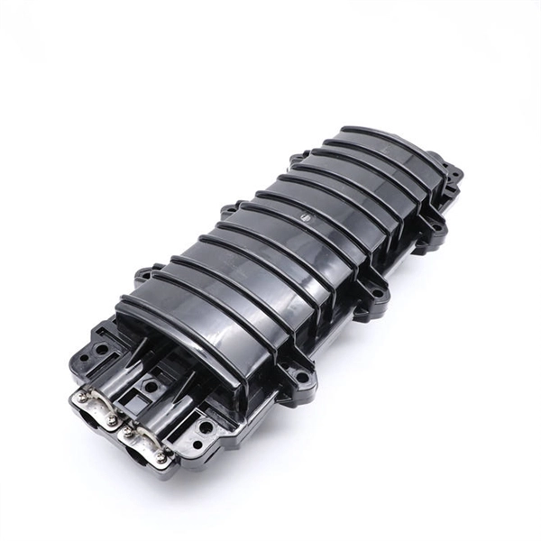
Explore verified suppliers offering low-price fiber optic splice boxes, ideal for wholesale. With options from 24 to 144 cores, start your purchase from 1 unit at an average price around $17. This fiber optic splice box is an outdoor fiber optic splice closure used to protect the twisting and joining (splicing) of fiber optic cables. These splice boxes are not made for in-house, off-the-shelf cabling solutions. Instead, they are for installation by professionals laying new fiber optic. Check each product page for other buying options. Price and other details may vary based on product size and color. Need help?. All products' documentation is published in PDF (Portable Document Format), which requires Adobe Reader (ver. 5 and newer) software for viewing. Though we pay utmost attention, we cannot guarantee, that published materials are free of errors and diversities. These lapses cannot be a basis for any. Longevity: Properly installed plastic splice boxes can reliably perform for 10–15 years or more, depending on climate and usage conditions. Best for: Telecommunications, low-voltage systems, residential wiring, and temporary installations where cost and ease of installation are priorities. These kits ensure minimal signal loss and maximum reliability in telecommunications, data centers, and broadband networks. Proper splicing maintains signal.
[PDF]
