Instead of relying on assumptions, this guide offers a clear-eyed look at how to properly secure your fiber infrastructure, moving beyond the myths to implement practical, layered defenses that provide real-world protection for your organization's most sensitive data. For manufacturers and industry professionals involved in creating, deploying, or maintaining these critical systems, ensuring the robust and reliable securement of fiber optic cables is paramount. “Securing” fiber optic cable goes beyond just preventing it from moving; it encompasses protecting its. Fiber optic cables enable high-speed, long-distance data transfer, forming the backbone of modern communication. Yet, outdoors, they face temperature swings, moisture, UV exposure, rodents, and human interference. Protecting them is essential for long-term reliability. This guide covers how to. Fiber optic and ACSR (Aluminum Conductor Steel Reinforced) cables play a critical role in modern infrastructure, including power transmission and telecommunications. However, these cables face several challenges that can compromise their performance and longevity. If you are an optical engineer or a fiber optic network operator, you need to know how to protect your cables from these threats and ensure. An effective fiber optic network security plan acknowledges these potential weak spots and addresses them head-on. Before beginning any installation, safety.
[PDF]

To use a power meter for fiber optic testing, always clean connectors first with lint-free wipes or click-to-clean tools. Select the correct wavelength and set your reference. You measure optical power in dBm or insertion loss in dB. Consistent procedures ensure accuracy. Verify light travels from. The most basic fiber optic measurement is optical power from the end of a fiber. This measurement is the basis for loss measurements as well as the power from a source or presented at a receiver. Typically both transmitters and receivers have receptacles for fiber optic connectors, so measuring the. An optical power meter measures the strength of light traveling through a fiber optic cable, giving you a reading in dBm (decibels relative to one milliwatt). This article will guide you through the methods, instruments, and key considerations for measuring fiber. Fiber optic cabling is the high-performance core of today's datacom networks. As network speeds and bandwidth demands increase, fiber performance requirements have become more stringent. Fiber testing is more important than ever. An OPM uses a photodiode to generate an electrical current proportional to optical power.
[PDF]
Fiber Optic Polarization Extinction Ratio Benchtop Meter for wavelengths from 850 nm to 1650 nm. ER = 30dB for wavelengths from 850 nm to 1290 nm and ER=35dB for wavelengths longer than 1290 nm. Receptacle is not included. Input power is up to 1 mW. Description Handheld Type; 400 to 2400 nm; Extinction Ratio Range 30, 35, 40 dB; Extinction Ratio Accuracy ±1 dB; Angular Accuracy ±0. 5°; Adapter Type FC/PC, ST, E2000. The PEM-400 is an instrument developed for high-volume testing of the polarization extinction ratio (PER) of polarization maintaining (PM) components such as fiber array units (FAU) and external laser small form-factor pluggables (ELSFP). A polarizer is rotated in front of a high-speed power meter. The ERM-202 is a rotating-polarizer polarization extinction ratio meter. It is available in single or dual channel versions. The ERM-202 combines low noise circuitry with a high resolution stepper motor to achieve a PER dynamic range of 50 dB and angle resolution of 0. It is widely used in. It features unmatched low cost, all wavelength options, a large dynamic range, and high resolution. The design adds a rotary polarizer to an optical power meter.
[PDF]

When you connect two 1000BASE-T switches with SFP ports to achieve Gigabit Ethernet, there are two methods: through standard Ethernet cable plugged into the built-in Ethernet ports of each switch, or use the SFP ports with a copper SFP module. 🎥 In this video, I show you how to connect two different branded switches using SFP modules and fiber optic cables. Whether you're using Cisco, Planet, TP-Link, D-Link, Ubiquiti, or any other brand — the key is understanding SFP compatibility. Before moving ahead, let us discuss some basics about standard Ethernet cables and 1000BASE-T (IEEE 802. Network topology refers to the way in which the links and nodes of a network are arranged in relation to each other. What Is a 10Gb SFP Module? A 10Gb SFP (Small Form-factor Pluggable) module is a compact, hot-swappable transceiver used to establish high-speed fiber. Did you swap one of the fiber connectors at one of the endpoints? Meaning, take off the housing of the fiber connector, and swap a and b. You'll find SFP / SFP+ specs on the datasheets for the switches. They're free to view and download from Cisco. Cisco also publish a GBIC /. Most modern fiber-enabled network switches require an SFP transceiver module featuring a duplex (two strand) multimode OM3 or duplex single mode OS2 connection with LC connectors. Direct attach cables with pre-terminated SFP connections may also be used. Download the Application PDF SFP transceiver.
[PDF]

Learn how to monitor SFP optical power on Cisco switches, interpret Tx/Rx levels, and troubleshoot fiber link issues. Step-by-step CLI commands, model-specific guidance, and best practices included. In this article, we will break down the key factors influencing TX/RX power, explain how to calculate the optical power budget, and provide actionable insights for optimizing your network's performance using SFP modules. SFP (Small Form-Factor Pluggable) modules are compact transceivers that allow. SFP (Small Form-factor Pluggable) optical modules are compact, hot-pluggable transceivers that enable network equipment to connect seamlessly to fiber and copper links. Even if an interface appears up, degraded Tx/Rx levels can cause intermittent flapping, packet loss, or err-disabled states. Think of it as the “translator” for your network equipment, converting electrical signals into optical signals. The most two important factors of the SFP transceiver: Output power (TX power) and receiver sensitivity (RX sensitivity). The optical TX power is the signal level leaving from that device, which should be within the transmitter power range. The RX sensitivity is the incoming signal level being. In current network communication, SFP optical modules are an indispensable physical foundation for building network channels. They form high-speed channels for optical signal transmission. Therefore, to ensure their.
[PDF]

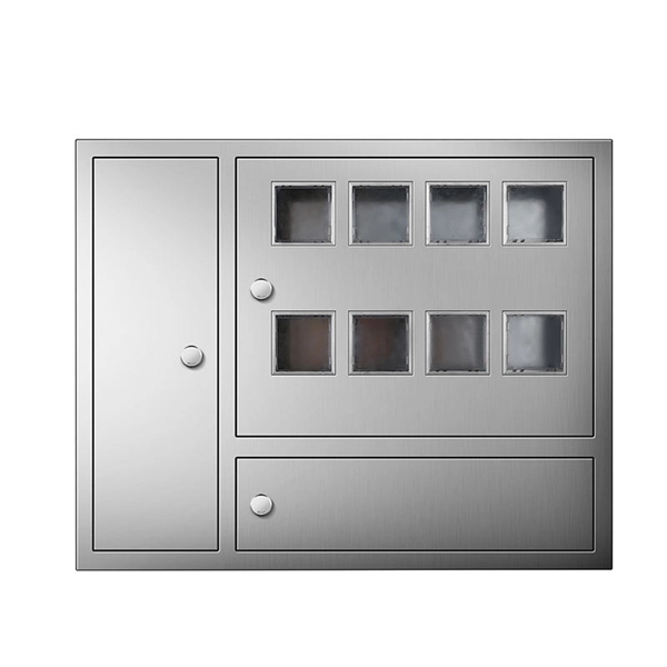
In this video, we'll show you how to connect an energy meter to a distribution board (DB) safely and efficiently. energy meter connection with distribution box How to Connect an Energy Meter to Your Distribution Box Easily Steps to Properly Connect Your Energy Meter to a Distribution Box. It plays a vital role in ensuring the safe and efficient distribution of electricity throughout the premises. What is the wire from the meter to the breaker box? Also. Always begin with disconnecting the main supply before accessing any enclosure containing distribution components. This prevents arc faults and ensures safety when modifying or inspecting current paths. This “meter to panel” wiring establishes the pathway for all incoming electrical power from the grid to the home. Its primary function is to safely and reliably. Distribution Board aslo know as “Panel Board”, “Switch & Fuse Board” or “Consumer Unit” is a box installed in the building containing on protective devices, such as circuit breaker, fuses, isolator, switches, RCDs and MCBs etc. The electric main supply (230V AC & 120V AC in US) is connected through. Changed Texas's reference diagram for the 3 wire network 120/208 Volt single phase self-contained Revised Figures 13, 14, 14b. Limited the meter location from pad mount transformer for PSO. Removed unistrut being listed as an alternative means for mounting the meter box. APCo and TX do not allow.
[PDF]
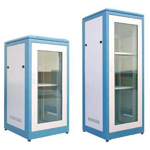
Every temporary power distribution box has several important components that work together to deliver safe, efficient power: These boxes use either 120/240 VAC single-phase or 120/208 or 277/480 VAC three-phase power sources. Temporary power distribution boxes are a budget-friendly way to supply electricity to a remote area. You can use them to power electrical equipment, lighting systems and more. Compared to other temporary power solutions, a power distribution box provides utility, safety and efficiency at an. Temporary power distribution boxes provide a safer way to manage power while keeping your workspace tidy. These versatile units work great for construction sites, entertainment events, and disaster recovery operations. Modern solutions rely on portable. Whether you need an industrial portable power station, a complete jobsite power station, or help managing temporary wiring and distribution, this will help you stay compliant with all the necessary requirements. Getting the selection wrong means more than inconvenience—it can mean shutdowns, damaged machinery, or worse.
[PDF]
The per-unit ranges commonly appear as $1,000-$2,500 per major component (panel or service upgrade) and $2-$8 per linear foot for wiring, depending on accessibility and installation complexity. The current total tariff rate on Electrical Wiring & Conduit from Tajikistan is 19. This is composed of the following layers: MFN base rate: 4. 5%; Section 122 surcharge: 15%. How much will it cost to import Electrical Wiring & Conduit from. What type of plugs and sockets are used in Tajikistan? When you are going on a trip to Tajikistan, be sure to pack the appropriate travel plug adapter that fits the local sockets. But what do those electrical outlets look like? In Tajikistan, types C and F are the official standards. 67 times less expensive than the world average. Tajikistan ranked 150th out of 197 countries by cost of living and the 153rd best country to live in. The average salary after taxes in Tajikistan is $216, which is enough to cover living expenses. Typical total project ranges for a residential electrical upgrade are $2,500-$8,000, with larger full-panel or service-upgrade jobs running $6,000-$15,000 in some markets. Get free. Brilltech Engineers Pvt. Ltd is the one you can reach. We have a highly experienced team, well-loaded manufacturing unit and a lot more to match up the ever-evolving needs of our customers. Moreover, our focus on maintaining high quality and attaining customer satisfaction stands us ahead of the.
[PDF]

In this video, we'll walk you through the process of resurrecting y. The test sets display a laser warning icon when the laser source is active to alert the user about a potentially dangerous situation. It is recommended to: Deactivate the laser before connecting or disconnecting optical cables or patchcords. more Is your optical power meter showing no signs of life? Don't worry; we've got you covered! In. Introduction The RP460 Optical Power Meter is an ultra low cost, and compact power meter used for verifying both absolute and relative power across any given fiber. This document will serve as an overview of the major features and functions of the device and will offer tips for trouble shooting. Fiber Optical Powermeter User Manual | FS Title Author Subject Keywords Created Date. The OPM1315 is a newly developed portable optical power meter. It is equipped with a 1. 0 mm large area detector so that stability and reliability can be enhanced effectively. This unit is designed to fit the hand comfortably, and can be used for installation, debugging, and maintenance of any fiber. ments to the instrument's performance and functionality. The figures given in this manual ion of this manual to ensure the accuracy of its contents. However, should you have any questions or fi gistered users with a variety of information and services. Please allow us to serve you best by.
[PDF]

How to Use Optical Power Meter TR-504 | Optical Power Meter Working| Testing OPM, VFL, RJ45 | TRICOM In this video, we walk you through how to use the TRICOM TR-504 Optical Power Meter and explain how it works. Learn how to test fiber optic cables, OPM, VFL . Optical power meters are a key element in the optimization and maintenance of such optical networks and of their components. In this article, learn: What is an optical power meter? An optical power meter (OPM) measures the power levels of light signals in devices that transmit data or power using. An optical power meter measures the strength of light traveling through a fiber optic cable, giving you a reading in dBm (decibels relative to one milliwatt). The basic process is straightforward: turn the meter on, set it to the correct wavelength, clean your connectors, plug in, and read the. OPM interface: insert the fiber to be tested, test the optical power. An optical power meter is a tool that measures the number of optical power in a cable is fiber-optic. It helps engineers verify the performance of optical fiber systems, ensuring that the signal strength meets requirements, and is an essential tool for communication network maintenance and troubleshooting.
[PDF]

The core measurement procedure follows five steps: Turn on the meter and let it warm up. Most meters need a brief stabilization period before readings are reliable. Check your model's manual, but a minute or two is typical. Set the wavelength to match your light source. Fiber loss is the difference between the power when light is coupled from the transmitting end to the fiber and the power when the light reaches the receiving end. Generally speaking, when measuring the. An optical power meter measures the strength of light traveling through a fiber optic cable, giving you a reading in dBm (decibels relative to one milliwatt). The basic process is straightforward: turn the meter on, set it to the correct wavelength, clean your connectors, plug in, and read the. A power meter and light source are essential test tools that work in tandem to measure fiber optic cable loss and evaluate the quality of optical links. They provide the data necessary to quantify signal loss and pinpoint issues that could impact network performance. Here's how they work: A power. You measure optical power in dBm or insertion loss in dB. Verify light travels from transmitter to receiver. We'll give you the basic information you need and provide some printable references.
[PDF]
Chad Powers is an American television series created by and, starring Powell in the role. Developed from an skit by, the show follows Russ Holliday after he disgraces himself on the field while serving as a star quarterback at a major college program. After ruining his reputation, Holliday undergoes a physical transformation, with the h.
[PDF]

It consists of 5 buttons. A power button, a button to turn on the VFL, a lambda button to set the wavelendth, a REF button, and a dBm/W button to set the unit of power. First, you check the initial power of a light signal. Then you check its power at the other end of optical. OPM interface: insert the fiber to be tested, test the optical power. REF/dB key: Short press the dB to switch unit, click once nW/dBm/dB to enter the upper clear data, press and hold until REF is displayed on the screen, and set the current optical power as reference value, enter the relative. There are two buttons on this meter. One is the power button, used to turn the meter on/off. At the top, there is a sensor that detects the light beam. The. at -22 (or 25 with tone on)). To do this you. Active Equipment Power Measurement Fiber Continuity Patch Cable Testing Check MM Reference Cables - Dual OWL MM Sources Check MM Reference Cables - WaveSource MM Sources Check SM Reference Cables - Laser OWL SM Sources Check SM Reference Cables - WaveSource SM Sources. Power-off: Press and hold “MODE” key for 2 seconds or more until “OFF” displays on the screen. Note: This instrument will shut down automatically without receiving any operation instruction for 10 minutes. Function selections: It.
[PDF]
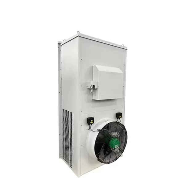
This paper presents a new liquid-cooling technology for uninterruptible power supply (UPS) units in which an air-cooling system is combined with an indirect water-cooling system based on direct-chip coolin.
[PDF]

An optical module's actual transmit power measured by an optical power meter is lower than the nominal transmit power of the power module. The possible causes are: Bores of the optical module are contaminated. Stable optical power is the foundation of every high-capacity optical transport system. Even minor deviations—whether too high, too low, or unstable—can impact signal integrity, trigger service alarms, or interrupt traffic on DWDM, OTN, or long-haul optical line systems. This is the domain of Cell-to-Module (CTM) power loss, a series of. This paper reviews methods for reducing different optical and electrical loss mechanisms in PV modules and for increasing the optical gains in order to achieve higher CTM ratios. Various solutions for optimizing PV modules by means of simulations and experimental prototypes are recommended. Have you ever experienced an unexpected network outage due to the failure of an SFP/SFP+ optical transceiver? Network outages can bring your ability to communicate and work to a halt, and your IT team will likely be frantically looking for a solution. It is important to understand how to. This article provides an in-depth analysis of two key performance indicators of optical modules: transmitter power and receiver sensitivity. Transmitter power characterizes the average optical power output from the laser under rated conditions, while receiver sensitivity indicates the minimum.
[PDF]