
This comprehensive guide breaks down the internal structure, core components (TOSA, ROSA, lasers), and operational mechanisms of SFP optical modules, enriched with technical insights and real-world applications. Optical Modules (also known as Optical Transceivers) are critical components in fiber optic communication systems. As the core optoelectronic devices operating at the Physical Layer of the OSI model, their primary function is to perform electro-optical and photo-electric conversion during signal. In the era of 5G, AI, and high-speed data centers, optical modules serve as the core bridge for converting electrical signals to optical signals (and vice versa), enabling fast, reliable data transmission across networks. They are used in fiber optic communication systems to transmit data over long distances with minimal loss and interference. This article systematically identifies common anomalies during optical module installation. Combining hardware principles with practical experience, it. When the industry speaks of optical modules, it refers specifically to small, hot-swappable packaged optical modules, which are used on equipment ports and can be hot-swapped during operation, and are mainly used to convert the electrical signals in equipment (usually switches or router equipment).
[PDF]

In this tutorial, I will show you how you can connect the Optocoupler to Arduino, read the data as Analog or Digital, and if necessary convert the analog values to digital, and how to reduce noise from the sensor. The Infrared Slotted Optical Optocoupler Module is a device that uses infrared light to transmit signals between two electrically isolated circuits. It consists of an infrared emitter (LED) and a photodetector (phototransistor) housed in a slotted enclosure. When an object passes through the slot. Slotted Optocouplers (Photo Interrupters) are very useful sensors, often included in Arduino projects to detect position of moving objects, measure speed of rotation, or linear motion, frequency of events, and many others. They are easy to use, but it is important to understand how they work, so. This tutorial is a comprehensive, practical guide to the Speed Sensor / Tacho Sensor (Slot-Type Optocoupler) (Leobot Product #245). Moreover, a simple application is programmed that shows how to wire and how to program an Arduino when working with the module. In this tutorial, the module is used as an “digital input board”. If you want to use the. In this project, I will talk about Phototransistor Optical Interrupter Switches (Opto Coupler) Module, how this module works and helps in determining the speed of a rotating object and finally I will show you how to Interface Optical Interrupter Switch Sensor with Arduino and measure the speed of a.
[PDF]

This is a simple video showing how to install a 850nm fiber optic link using SFP transceivers between 2 10 Gigabit backbone switches. Covers transceiver inst. As a leading provider of fiber optic solutions, Weunion offers a wide range of SFP-compatible products, including optical transceivers, DAC/AOC cables, LC patch cords, and MPO/MTP assemblies. This guide explores the essentials of SFP connectivity, installation best practices, and how Weunion's. These transceiver modules are hot-swappable input/output (I/O) devices that plug into 100BASE, 1000BASE and 10GBASE ports (for SFP+), which connect the module port with the fiber-optic or copper network. This document contains these sections: The SFP transceiver modules are hot-pluggable I/O. An optical module is an optoelectronic conversion device that transmits data by converting electrical signals into optical signals. Common types of optical modules include SFP, SFP+, SFP28, QSFP, QSFP28, etc. Different types of optical modules have different performance parameters such as speed. The 1310 nm WWDM solution, 10GBASE-LX4, requires the use of a mode-conditioning patch cord on multimode fiber to achieve its specified range of operating distances. more Audio tracks for some languages were automatically generated. Learn more This is a simple. One of the most widely deployed optical solutions for short-distance 10G links is the multimode SFP+ transceiver, commonly referred to as a 10GBASE-SR module.
[PDF]
This video will show you how to wire a Painless Performance headlight relay into your OBS Chevy / GMC truck or Tahoe to keep the low beams on when you run the high beam lights for much better light coverage in night driving conditions. more. If your headlights suddenly seem too high, too low, or uneven, you likely need to adjust the beam pattern on your headlights. In many cases, poor headlight aim comes from extra weight in the rear of the vehicle. For example, a loaded trunk, hunting gear, tools, or a trailer can push the back end. When we want to replace and upgrade our car headlights, we will pay attention to their brightness and beam pattern. But there is one important factor that is often overlooked - the cutoff line. You can. A blown out low beam bulb can make it difficult to see at night and driving with your high beams on all the time can make it difficult for other drivers to see. Fortunately, fixing a bad low beam is a straight forward process in the majority of vehicles that can be done by most people without just. This DIY will explain how to hookup your DRL's to stay on with your low beams WITHOUT running a switch in the cab. One 30 amp max fuse holder 5. Length of assorted color 14-16 guage wire 6. Female connectors (blue) 7. The right pattern illuminates potential hazards, complies with legal standards, and ultimately keeps you safe. more Audio tracks for some languages were automatically.
[PDF]

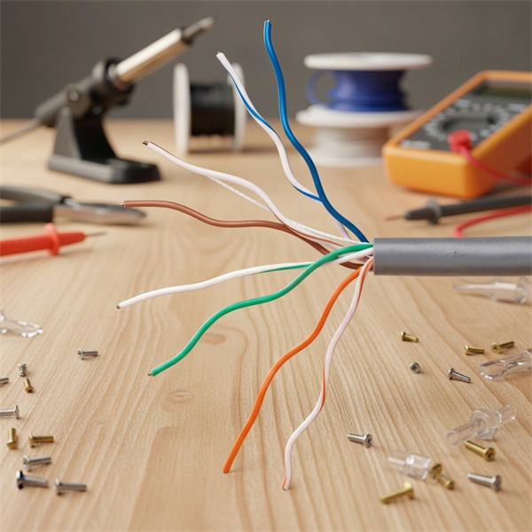
One of the core advantages of MPO patch cords is their high-density integration. Traditional patch cords have only 1-2 cores per cord, while MPO patch cords can integrate 12-48 cores, enabling multi-port connections with a single cord. Fiber cores are the heart of fiber optic cables, transmitting light signals that carry data. Made from either high-quality glass or plastic, the core plays a critical role in determining the cable's performance. The total number of cores for a 1pc fiber patch cable is calculated as the number of. Multi-core patch cords are fiber assemblies containing multiple fibers within a single cable jacket, typically available in 4, 6, 12, and 24-fiber configurations. The outer sheath is clearly marked with core count indicators. MTP/MPO cables are a class of high-density multi-core fiber optic connectivity solutions widely used in data centers and telecom networks, which are designed to achieve fast connection of multi-core fiber optics through a single interface. In the context of accelerating digitalization, the rational. The 16-core MPO patch cord, a high-density optical fiber connector, has become an ideal choice for 400G networks and beyond due to its superior optical performance, flexible compatibility, and efficient cabling capabilities. This report analyzes the key technical parameters, primary application.
[PDF]

This quick-reference guide focuses on what to measure, how to interpret results, and what to do when findings indicate marginal performance. Whether you're a network engineer validating new inventory or an integrator preparing for deployment, knowing how to test optical transceiver modules can save time, reduce failures, and ensure SLA compliance. Unchecked optical modules can cause: Testing ensures compliance with IEEE 802. 3 and MSA. This article provides a comprehensive guide on measuring key performance indicators to evaluate the functionality of optical modules, with a specific focus on the sfp28 transceivers. A comprehensive understanding of the working principle of an optical module is essential for determining the. Evaluating the performance of optical modules is a practical discipline: you must verify optical power and signal quality, confirm electrical/optical compliance, validate link-level behavior under real traffic, and document results in a way that supports reliability engineering. This. The optical module serves as a crucial component in optical fiber communication systems, operating at the physical layer, which is the lowest layer in the OSI model. Its primary function is to achieve optoelectronic conversion by converting electrical signals into optical signals and vice versa.
[PDF]

Testing solar panels is easy with a multimeter! To test the current, simply connect the multimeter to the panel's output. Set it to read DC current. A multimeter is an indispensable tool for anyone working with solar panels, allowing for accurate measurements and diagnostics. It empowers users to assess the performance, identify faults, and ensure optimal energy production. Without proper testing and maintenance, solar panels can suffer from. In this article, you will learn the step-by-step process of testing your solar panels using a multimeter. We will cover the essential tools you need, the specific measurements to take, and how to interpret the results. By the end of this guide, you will be equipped with the knowledge to diagnose. With just a simple tool—a multimeter —you can quickly measure your panel's voltage and current. This helps you spot issues early and keep your system running efficiently. Connect the multimeter. 🔋 Learn how to test solar panels using a multimeter — step-by-step! I'll show you how to safely check voltage, amperage, and open-circuit power, so you can confirm if your panels are producing the watts you expect. Perfect for DIY solar builders, RV owners, o. We'll also introduce the Honeytek HK78G 2000V PV Multimeter, a professional tool designed for solar testing. Honeytek, a global.
[PDF]
Remove the module from the receiver frame. Use the Allen wrench to remove the module cap screws located at the top, middle and bottom of the module (Figure B). For 37 and 16/16 position use a Phillips screw driver to remove the (2) 2-56 screws. Terminating fiber optic cables essentially means putting connectors on fiber optic cable so that you can connect the cable to various devices or network components. Think of it as the equivalent of connecting the dots in a complex puzzle; without proper termination, the whole system can break down. How to remove/disconnect fibre cable from Telus modem? Pull the green thing from the metal thing If you pull it out make sure to put the fiber connection in a plastic bag or blow it with air before plugging it back in, Fiber laser modules and a single spec of dust/lint/crumb can affect your speeds. Terminating fiber optic cable is a crucial step in the installation process, as it ensures a reliable and efficient connection. The contact can only be installed from one side. Ensure that the contact is squared up with the corresponding module location. Once in place, pull the wire. The transceivers for the router are hot-removable and hot-insertable field-replaceable units (FRUs). After you remove a transceiver or when you change the media-type configuration, wait for 6. IN THIS VIDEO I WILL SHOW YOU How to Disconnect Optical Fiber Cables from the Connector #DISCONNECTOPTICALFIBER.
[PDF]

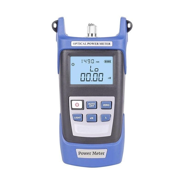
How to Use Optical Power Meter TR-504 | Optical Power Meter Working| Testing OPM, VFL, RJ45 | TRICOM In this video, we walk you through how to use the TRICOM TR-504 Optical Power Meter and explain how it works. Learn how to test fiber optic cables, OPM, VFL . Optical power meters are a key element in the optimization and maintenance of such optical networks and of their components. In this article, learn: What is an optical power meter? An optical power meter (OPM) measures the power levels of light signals in devices that transmit data or power using. An optical power meter measures the strength of light traveling through a fiber optic cable, giving you a reading in dBm (decibels relative to one milliwatt). The basic process is straightforward: turn the meter on, set it to the correct wavelength, clean your connectors, plug in, and read the. OPM interface: insert the fiber to be tested, test the optical power. An optical power meter is a tool that measures the number of optical power in a cable is fiber-optic. It helps engineers verify the performance of optical fiber systems, ensuring that the signal strength meets requirements, and is an essential tool for communication network maintenance and troubleshooting.
[PDF]

A wiring diagram for a photocell and timeclock controller provides a step-by-step guide for installing and connecting all the components in a light system. It shows exactly how each component fits into the overall scheme of things, as well as what wires to use and which connections to. Intelligent Lighting Controls' wiring diagrams show detailed schematics of our solutions. A lighting control module is the “control center” for your lighting system. It acts as a bridge between your physical lighting fixtures and the smart systems that manage them. Instead of relying solely on traditional wall switches, you can control your lights via remotes, mobile or web apps. This guide will discuss the steps needed to integrate with URC Total Control. Commission CSI Controllers Step 2. Locate/Download latest TCM files/Module Step 3. Network Setup Step 6. Supports DALI V2 compatible switches and sensors, works out of the box. Simple and easy setup. ControlByWeb® IoT controllers are a great fit for lighting control in edge applications. Understanding the components that make up a modern lighting system, and how they relate to one another is key to ensuring the best performance and.
[PDF]

A good laser source for a singlemode link will have a power output of ~ +3 to +6 dBm - 2-4mw - coupled into the fiber. Tx power (transmission power) refers to the intensity of the optical signal output by the transmitting end of the optical module. However, in practical use, we adopt the average Tx power. These modules, including SFP, SFP+, and SFP28, are widely used in enterprise networks, data centers, and carrier-grade deployments. Optical loss is measured in “dB” which is a relative measurement, while absolute optical power is measured in “dBm,” which is dB relative to 1mw optical power Loss is a negative number (like –3. 2 dB) while power measurements can be either positive (greater than the reference) or negative (less than. SFP (Small Form-Factor Pluggable) modules are compact transceivers that allow for high-speed communication between network devices. They are essential in applications like telecommunications, data centers, and enterprise networks. Generally, the power levels are specified in terms of transmit (TX) power and. Transmit power is the power at which the transmitter of an optical transceiver module transmits optical signals in dBm. When the signal received is outside of the range, there is a.
[PDF]
Optical Modules Market Segments - by Product Type (Transceivers, Receivers, Transmitters, Amplifiers, and Others), Application (Data Centers, Telecommunication, Enterprise Networking, and Others), Distribution Channel (Online Stores, Direct Sales, Indirect Sales, and Others), Form. Optical Modules Market Segments - by Product Type (Transceivers, Receivers, Transmitters, Amplifiers, and Others), Application (Data Centers, Telecommunication, Enterprise Networking, and Others), Distribution Channel (Online Stores, Direct Sales, Indirect Sales, and Others), Form. Optical Module Chip Market size was valued at US$ 823 million in 2024 and is projected to reach US$ 1. 52 billion by 2032, at a CAGR of 8. The Optical Module Market grew from USD 26. 53 billion in 2025. Data centers will keep dominating optical module demand as AI and cloud drive revenue growth through 2030. Optical module demand is being pulled in two directions at once, faster bandwidth for dense networks and tighter constraints on power, security, and lead times. With global R&D projected to. The global Optical Modules market is projected to grow from US$ 17590 million in 2024 to US$ 56786 million by 2031, at a CAGR of 15. 8% (2025-2031), driven by critical product segments and diverse end‑use applications, while evolving U. tariff policies introduce trade‑cost volatility and.
[PDF]

In this tutorial video, we will show you step-by-step how to safely and effectively remove an optocoupler from a circuit board using desoldering wick. We will walk you through the tools you will need, the proper technique for using the desoldering wick, and the precautions to take to av. more In. Whether you're replacing a faulty component, salvaging parts from an old board, or correcting a soldering mistake, knowing how to desolder effectively is essential. This guide will walk you through the tools, techniques, and best practices for desoldering components from a circuit board safely and. Desoldering is a process that removes the solder and components from a printed circuit board or any other type of electronic assembly. This is a meticulous process and it can easily damage the board, or the components, if not properly done. Thus, it is important to know how to desolder properly. If you're desoldering a battery from a circuit board, use flush cutters to cut each wire one-at-a-time to isolate the battery before you desolder the wires. Whenever possible, create an indirect path by soldering connectors onto the battery and the circuit board. This reduces the chance of an. Sorry, an unexpected error has occurred. Why Publish? The Ultimate Guide to Desoldering: From using desoldering irons to sketchily knocking breadboard components off on the side of a table, there are tons of ways to remove components from a circuit board.
[PDF]
Visible light communication (VLC) is an advanced, highly developed optical wireless communication (OWC) technology that can simultaneously provide lighting and high-speed wireless data transmission. A VLC system has several key advantages: ultra-high data rate, secure communication channels, and a. In some situations, visible light communication (VLC) has considerable advantages over the more generally utilized radio frequency (RF). This chapter delves into the fundamentals of VLC, beginning with an insightful exploration of its background and subsequently addressing the advantages and. Efficiency, durability and long life span of LEDs make them a promising residential lighting equipment as well as an alternative cheap and fast data transfer equipment. Appliance of visual light in data communication by means of LEDs has been densely searched in academia. In this paper, we explore. Visual light source of Lano Technology is designed to meet the demands of various industries, our visual light sources deliver exceptional brightness and clarity, ensuring optimal visibility for your applications. With a wide range of product models available, you can find the perfect solution for. Below find pdf documentation available for Visual Lighting. You can also view the Visual Lighting Manual in web help format. Visual is powerful lighting software engineered to bring.
[PDF]

It emits a stable red light driven by a constant current source, which is coupled into the optical fiber through an interface to perform fiber fault detection functions. These include checking fiber connectivity and locating faults such as fiber breaks and bends. The B5 Rechargeable Red Light Pen is a professional 650nm visual fault locator designed for fiber optic network maintenance, installation, and troubleshooting. Its advanced rotary automatic lift laser head ensures smooth operation, while the integrated LED lighting improves visibility in low-light. Luxbond LBTEK Fiber Optic Red Light Pen (also known as a pen-style visual fault locator or fiber optic fault detector) uses a 650 nm semiconductor laser as the light source. Note: Meant for use with polished, terminated fiber cables. Always insert and remove the fiber connector without bending the connector to avoid breaking. The RPEN-210 is a necessity tool that should not be missing from any fiber plant manager or fiber optic installing technician. The Visual Fault Locator (VFL) Pen has a visible red light source centered on 650nm. Tool sends visible light over a fiber strand with a 10mW power, good enough to reach. ● Practical Design: Small size and lightweight, pen-type design with pouch make it portable. Design with a stainless steel head and aluminum body to prevent crash and dust, the case ground design prevents ESD damage efficiently Temp. Only registered users can write questions.
[PDF]