Learn how to safely wire a single-pole (one way) light switch in this beginner-friendly tutorial. Whether you're replacing an old switch or doing your first DIY electrical project, this guide will walk you through every step — no experience needed!. more. This page contains wiring diagrams for household light switches and includes: a switch loop, single-pole switches, light dimmer, and a few choices for wiring an outlet/switch combo device. That's because virtually all light switches that control 120-volt fixtures are single-pole switches. Most light switches are also single-throw, which. Summary: Fully explained wiring diagrams and photos show how to wire switches including: single switches, 3-way switches, 4-way switches, and dimmer switches. and Be Sure to Subscribe! Make sure the circuit power has been turned off, and mark the circuit breaker or fuse to indicate that work is. A distribution board or distribution box is where the main power supply is distributed to multiple loads. And all the switching and protective devices are installed in the distribution box. Single Phase Distribution Box generally consists of Double Pole MCBs, Single Pole MCBs, and RCCBs. Wiring a single light switch may seem like a daunting task, but with the right tools, a bit of patience, and this comprehensive guide, you'll be able to tackle this DIY project with confidence. Remember, while this guide provides detailed instructions, always prioritize safety and consult a.
[PDF]
A neat, well-organized subpanel bundles wires to conserve space and improve access. Ideally, wire groups are installed in layers and wires are bent at right angles to buses or breakers. Label short sheathing sections (slugs) to indicate which circuits wires serve. We cover everything from separating color-coded wires and securing them with ties to. Discover 7 DIY tips to organize your electrical panel for improved safety, easier troubleshooting, and efficient maintenance. Prevent hazards while making your home's electrical system more manageable. A disorganized electrical panel isn't just an eyesore—it's a safety hazard and troubleshooting. According to NEC (National Electric Code: Article 1 00-Definitions), a Main Panel (also known as Panelboard, load center, breaker box and distribution board etc. ) is a cabinet or cutout box which contains on controlling and protective devices (such as circuit breakers, fuses, switches etc. ) used to. Welcome to this live training session! ⚡ In today's tutorial, I'll be demonstrating how to arrange cables neatly inside a distribution bo. more See what others said about this video while it was live. If you're struggling with unsightly cords hanging around your cabinets, worry not! In this guide, we'll explore practical strategies to conceal those wires effectively. Before starting the process of.
[PDF]
In this guide, we will provide you with a step-by-step process to help you wire an electrical panel box safely and efficiently. Before you begin wiring an electrical panel box, it is important to gather all the necessary tools and materials. An electrical panel box, also known as a breaker box or a distribution board, is a crucial component of any electrical system. It serves as a central hub for distributing electricity throughout a building, ensuring that power is delivered safely and efficiently to all the required locations. In part two, learn how to install recessed lighting. Begin by laying out your lights templates. Shut off the power at the circuit breaker box. Drill holes in the ceiling, run the wiring, run the cable into the new box, mount the light and enjoy. Whether you are an electrical contractor or a construction brigade, knowing how to properly and safely install distribution boxes is the basis of ensuring the safe operation of the entire system. To understand how a breaker box works, it is helpful to. Hey, in this article we are going to see the Single Phase Distribution Box Wiring Diagram and Connection Procedure. And all the switching and protective devices are installed in the. Understanding load center wiring diagrams is essential for anyone who is involved in electrical installations or repairs. These diagrams provide a visual.
[PDF]
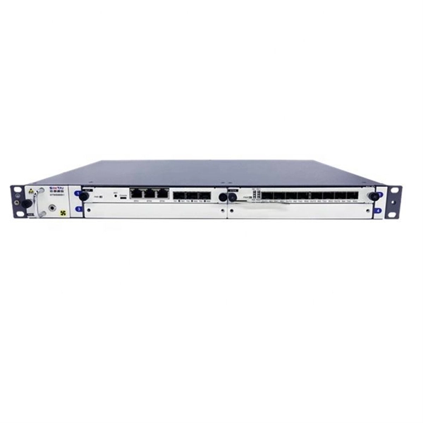
There are 48 bicolor LEDs (green/amber) for the first 48 SFP+ ports and 16 tricolor LEDs (green/amber/white) for the SFP-DD ports. The last set of LEDs pulse once in white before indicating the FC port status in green or amber. When it blinks white twice, it shows the status of the second port of the SFP-DD. The port status LEDs for the FC ports are arranged left and right to correspond to the upper and lower ports respectively in each pair. LEDs on the port side of the switch Table 1. LEDs on Cisco Catalyst 9500 Series Switches 1 Available only on switches with 10G ports. System LED Indicator System is not operational. System is operating normally. As a group or individually, the LEDs show information about the switch and about the ports Preventing Overload - Each port that provides PoE has a maximum power it can deliver. Three LEDs are used on each port. Ports on the Cisco Catalyst switch do not have LEDs. Not the question you're searching for? Each. Number of LEDs per port - Ports that cannot be split; for example, 1G ports must have 1 LED per port. Location - A port LED should be placed right above the.
[PDF]
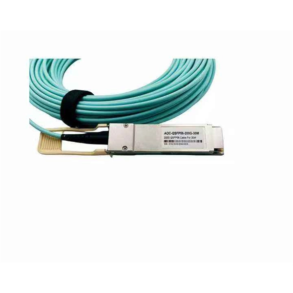
This beginner-friendly guide will walk you through the step-by-step process of fiber optic cable installation for each method, highlighting best practices, tools, and considerations. Proper connection of fiber optic cables is essential to harness these benefits fully, as even minor errors can lead to significant performance issues like signal loss. This article will guide you through the necessary tools, materials, and methods on how to connect fiber optic cables effectively. Starting with site surveys and permissions, to installing fiber optic cable and emphasizing the process as a key stage in mastering fiber optic installation, to the careful handling of cables and high-stakes splicing, each stage is critical. Discover the exact steps, adhere to stringent safety. Single family homes, apartments, condominiums and other multi-dwelling units are increasingly wired with fiber optic cable to future-proof installations and create more reliable, higher-bandwidth and faster speed network and video infrastructures. The processes. Running fiber internally involves extending this high-speed link from the service entry point to a centralized location, such as a dedicated media closet or network rack. This DIY effort is undertaken to maximize performance, improve aesthetics, or relocate the Optical Network Terminal (ONT) to a.
[PDF]

Insert the end of your fiber optic network line into the fiber optic connector on the converter box. Plug an Ethernet cable into the Ethernet port on the converter box and plug the other end into one of the Ethernet ports on the back of your Ethernet switch. As we speak I just have optic fibre (Community Fibre) connected to my Huawei modem / Linksys Velop which will be connected to a new POE switch (need to identify the best model to be compatible with my optic fibre extension project). The objective is to run 1 or 2 additional optic fibre from the. Connecting a fiber optic switch involves several steps, ensuring compatibility between the switch's ports and the fiber optic cable. Fiber optic switches utilize. Fiber optic cabling is increasingly used to connect network switches and other datacom equipment, especially in long-distance and mission-critical applications. Fiber provides: Increased internet signal bandwidth. Advantages Determine the length of the fiber run and choose either multi mode for runs under 1000 feet or single mode for runs over 1000 feet.
[PDF]
The Box Fill Calculator is an essential electrical installation tool that determines the maximum number of conductors, devices, and fittings that can be safely installed in electrical boxes according to National Electrical Code (NEC) standards. Calculate electrical box fill capacity and ensure NEC compliance for proper wire management and electrical safety. Click on any. Learn how to wire a distribution box step by step! This video shows real on-site footage of electrical installation, demonstrating safe and standardized wiring methods used by professionals. It serves as a central hub for distributing electricity throughout a building, ensuring that power is delivered safely and efficiently to all the required locations. The National Electrical Code (NEC) and Canadian Electrical Code (CEC) specify strict limits on how. In just a few steps you will find the wiring and assembly plan, including complete documentation in accordance with standards. This is the design philosophy which the browser-based distribution board configurator from Eaton is based on. Distribution board configurator for different types of. Hey, in this article we are going to see the Single Phase Distribution Box Wiring Diagram and Connection Procedure. And all the switching and protective devices are installed in the.
[PDF]
In this article, I'm going to describe how to set up Link Aggregation between two managed switches to provide connectivity, redundancy, and expanded bandwidth. Managed switches provide many advantages for a growing network, including support for VLANs, QoS, and Trunking. I touched on simple VLAN configuration a while back. in the United States and in other countries. App Store and the Apple logo are trademarks of Apple Inc., registered in the U. Google Play and the Google Play. Link Aggregation in UniFi allows you to combine two or more ethernet ports into one. The NVR is connect via Fibre to the USW as well. So. ? Any hints welcome! Archived post. New comments cannot be posted and votes cannot be cast. Imagine transforming multiple network cables into one giant, super-speed "data highway. " That's exactly what link aggregation does. It combines multiple Ethernet connections into a single logical connection, boosting speed, enhancing. Thank you for purchasing the Ubiquiti Networks® EdgeSwitch® XG. This Quick Start Guide is designed to guide you through installation and also includes warranty terms. TERMS OF USE: All Ethernet cabling runs must use CAT6A (or above). It is the professional installer's responsibility to follow local.
[PDF]
You can run the display arp command to view IP addresses and interfaces of servers directly connected to a switch. Since it is based on arp, it does only work for devices having an ip address in the network segment where you use that feature. So if not used in the management network, it may only be applied with L3 Switches. As far as I know it is not really the case. Ip device tracking can work on L2. Finding the IP address of your network switch is crucial for a variety of tasks, from configuring its settings to troubleshooting network connectivity issues. While it might seem like a technical hurdle, several straightforward methods can help you uncover this essential piece of information. This guide will go over how to find the IP address of the M4300 & M4250 and how to access the web interface of the switch. VLAN 1 of the switch is configured by default to receive DHCP. VLAN 1 is configured by. Is there a command that I can use through Putty to figure out the IP new IP address of the switch? Thank you! Edit: The switch is still isolated and is not connected to anything other than the workstation that I am using to configure it. Just hook back up to the COM port and look. Network switches are integral components of modern computer networks, facilitating efficient data transmission and connectivity among multiple devices. The INTERFACE field displays switch.
[PDF]
The LEDs have three possible states: no light, a steady light, and a flashing light. Flashing lights may be slow, fast, or flickering. This light shows whether your ONT is getting power. Solid Green: The ONT is powered on and functioning normally. What to check: Make sure the power cable is securely plugged into both the ONT and a working wall outlet. If you're using a power strip, check. The tables in this article provide detailed information about the possible appearances of the LED lights on each device, the possible causes of each state, and what you should do. Ensure your Fiber Jack is connected to the network and the LED lights are connected and working properly before moving. System activity and status can be determined through the activity of the LEDs on the switch. A single tricolor LED for each SFP-DD indicates the port status. When the SFP-DD LED blinks white one time, it shows the status of the first port of the SFP-DD. An ONT may also be called a Service box. If you're having issues and can't get your ONT to power up, contact us. It flashes green during the initialization phase, remains solid green after successful initialization, and turns red when a system fault occurs. When the Status light is red, you can use a PC. Help Centre topics. Fibre ONT devices and how they work.
[PDF]

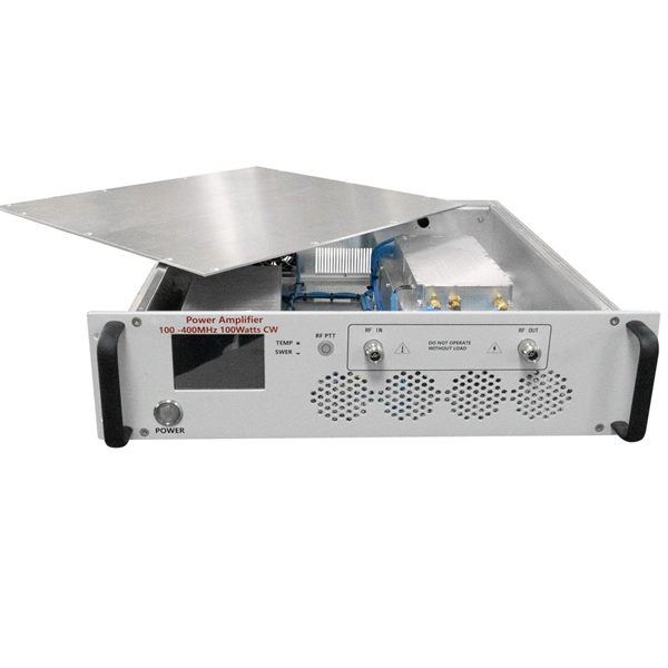
In today's video, we'll be unboxing the 9-Port Power Supply Box and demonstrating how to connect the cables to provide power to CCTV cameras. A CCTV power supply box sends power to all your cameras from one place. It helps keep things neat and makes your system easier to manage. In this guide, you'll learn how to install it step by step, choose the right type, avoid common problems, and keep your system running safely. Power supply boxes for CCTV are typically used in multi-camera installations instead of using single power adapters for each camera. The process is almost exactly the same if you. Installers of surveillance systems may simply control the power to various CCTV cameras using a CCTV power supply box, also known as a power distribution box (usually at the location of the DVR). This enables a cleaner camera installation. Surge protection can be accomplished in two ways. The power supply box is specifically used to transfer power requirements for all cameras plugged in on the system, to work. Security cameras use RG59U coax siamese wire or CAT5e networking cable to transmit video. Whether you are installing a power box for a new or existing camera system, it is important to understand how to connect cameras to a CCTV Power Supply Box. DC current is polarized meaning it has two leads, a.
[PDF]

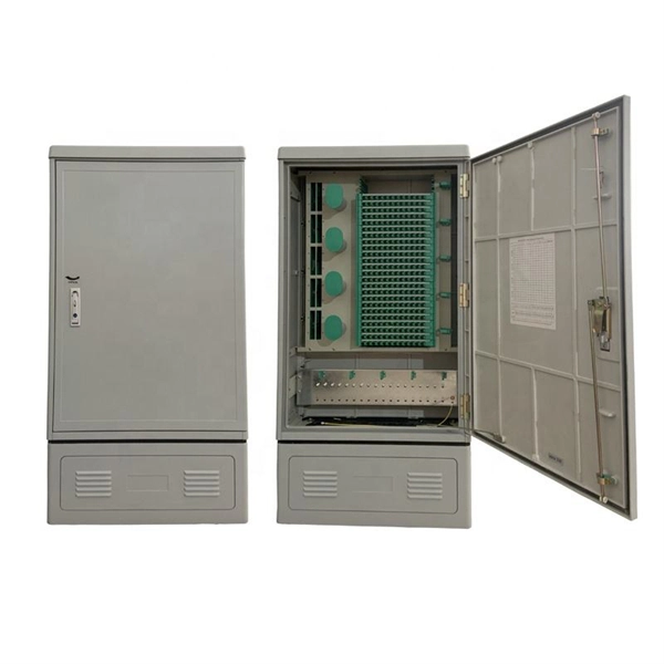
Learn how to install a distribution box safely and correctly. Covers wiring, placement, standards, and expert tips for a compliant setup. It takes the incoming power and safely distributes it to different. In this video, we'll walk you through the process of wiring a home distribution box with a detailed connection diagram. more Welcome to our channel! In this video. Whether you are an electrical contractor or a construction brigade, knowing how to properly and safely install distribution boxes is the basis of ensuring the safe operation of the entire system. It serves as a central hub for distributing electricity throughout a building, ensuring that power is delivered safely and efficiently to all the required locations. In modern electrical systems, cable distribution boxes (also known as electrical distribution boxes or distribution boxes) play a crucial role as the key hub for managing, distributing, and protecting circuits. Whether it is residential buildings, commercial facilities or industrial sites, the. In this guide, we will break down the key elements involved in connecting the main power supply to your home, providing a clear path for a successful setup. We will focus on the critical parts of the system, from basic components to step-by-step assembly procedures. Whether you are looking to.
[PDF]

In this complete wiring diagram guide, we will walk you through the step-by-step process of wiring a mag starter. We will explain the purpose and function of each component, provide clear diagrams, and offer expert tips to ensure a successful installation. Whether you're a beginner or an. For proper integration of an electromagnetic securing device, ensure the power supply matches the specified voltage–typically 12V or 24V DC. Incorrect voltage can cause malfunction or reduced holding force. Use a regulated power source to prevent current fluctuations that might trigger false alarms. Understanding the wiring diagram of a magnetic starter is essential for technicians and electricians who work with electric motors. This diagram provides a visual representation of the components and connections involved in the operation of the starter. Once you have everything ready, you can proceed with the installation process. Begin by determining the appropriate position for the magnetic lock on the door. Quick guide on how to wire an access control system with power supply, lock, and exit button. more Quick guide on how to wire an access control. Installing a magnetic door lock can be a cost-effective and reliable way to secure your doors. These locks use an electromagnetic current to keep the door securely closed, and they are commonly used in commercial and residential buildings.
[PDF]

show interface - To view the configured IP address on the switch. These are the various commands referenced in this document: Updated Grammar and Formatting. Finding the IP address of your network switch is crucial for a variety of tasks, from configuring its settings to troubleshooting network connectivity issues. While it might seem like a technical hurdle, several straightforward methods can help you uncover this essential piece of information. This article provides a comprehensive guide to locating the IP address of a Cisco switch, covering various methods and tools available to network administrators and. Knowing the IP address of your switch is essential for network troubleshooting, configuration, and management. However, finding the IP address of a switch can sometimes be challenging, especially if you don't have access to its documentation or network infrastructure details. In this article, we. This guide will go over how to find the IP address of the M4300 & M4250 and how to access the web interface of the switch. Check the DHCP server to find the new lease from the switch. VLAN 1 default IP address. Two of them are Cisco ones the third one is a D-Link. My predecessor was managing them, unfortunately, when I inherited them I got zero information about it and. Configure the IP address on the switch. Do the next steps to set the system parameters on Catalyst switches that run Cisco IOS software. For details on how to connect to the Console ports of the.
[PDF]

In this video, we'll show you how to connect an energy meter to a distribution board (DB) safely and efficiently. energy meter connection with distribution box How to Connect an Energy Meter to Your Distribution Box Easily Steps to Properly Connect Your Energy Meter to a Distribution Box. It plays a vital role in ensuring the safe and efficient distribution of electricity throughout the premises. What is the wire from the meter to the breaker box? Also. Always begin with disconnecting the main supply before accessing any enclosure containing distribution components. This prevents arc faults and ensures safety when modifying or inspecting current paths. This “meter to panel” wiring establishes the pathway for all incoming electrical power from the grid to the home. Its primary function is to safely and reliably. Distribution Board aslo know as “Panel Board”, “Switch & Fuse Board” or “Consumer Unit” is a box installed in the building containing on protective devices, such as circuit breaker, fuses, isolator, switches, RCDs and MCBs etc. The electric main supply (230V AC & 120V AC in US) is connected through. Changed Texas's reference diagram for the 3 wire network 120/208 Volt single phase self-contained Revised Figures 13, 14, 14b. Limited the meter location from pad mount transformer for PSO. Removed unistrut being listed as an alternative means for mounting the meter box. APCo and TX do not allow.
[PDF]