In this blog, we'll walk through the standard procedures for installing racks and assembling MPO systems in modern data centers. Before any hardware is installed, detailed planning is essential. Rack placement must consider airflow, power distribution, cable routing, and physical. Proper installation of components in a data center server rack is crucial for optimal performance, efficient maintenance, and long-term reliability of your IT infrastructure. The term breaks down into two distinct phases: “racking” involves assembling and mounting servers, switches, storage devices, and networking equipment into. Best Practices for Data Center Rack and Stack Installation in 2025. Data centers are the backbone of modern technology, and ensuring their infrastructure is installed correctly can significantly impact performance and scalability. Data. However, before you get down to installation itself, it's necessary to prepare for it. A preparatory stage includes several important pre-installation steps that ensure smooth and durable functioning. These include: Choosing the right rack type. Server furniture differs a lot. Modern manufacturers. Four-Post Racks To mount two-post racks, the equipment has to be bolted to two vertical posts, in most cases at the front. They are simple, cheaper than other types, and occupy less space. They are a good choice for small IT rooms or closets with minimal depth requirements and lightweight devices.
[PDF]
Optical modules, also known as optical transceivers, are essential components that convert electrical signals to optical signals and vice versa. They form the backbone of long-distance, high-capacity data transport in modern telecom networks. A common question arises: “Are switches optical switching devices?” The answer is nuanced—optical transceivers combined with switches form a complete. Optical modules are essential components in modern communication networks, enabling high-speed data transmission over fiber optic cables. As the demand for faster and more reliable internet connections grows, understanding these devices becomes increasingly important. Deployed across fronthaul, midhaul, and backhaul. Optical transceivers are used for information storage, generation, and extraction between various devices within a data center. As AI models grow more complex and datasets balloon in size, traditional copper-based interconnects are. Modern data centers increasingly rely on interconnects for delivering critical communications connectivity among numerous servers, memory, and computation resources. Data center interconnects turned to optical communications almost a decade ago, and the recent acceleration in data center.
[PDF]

Optical modules (also known as fiber optic transceivers) are essential components in modern communication networks, enabling high-speed data transmission by converting electrical signals into optical signals and vice versa. Among various optical module form factors, SFP (Small Form-Factor Pluggable). A fiber optic transceiver (also called an optical transceiver) is a compact module that both transmits and receives data signals through optical fibers. It serves a dual purpose — transmitting electrical signals as light pulses and receiving light pulses to convert them back into electrical form. An optical module usually consists of an optical transmitting device (TOSA, including a laser), an optical receiving device (ROSA, including a photodetector), functional circuits,main control circuit board (PCBA), housing and optical (electrical) interface and other components. How do optical. At the heart of fiber optic technology lies a crucial component: the optical transceiver. Let's explore the key aspects of optical transceivers to help you navigate.
[PDF]
The European market for prefabricated and modular data centers is projected to grow to $4. 08 billion by 2034, driven by AI, 5G, and EU regulatory demands. Europe's digital transformation is literally being built on modules. Discover the top 10 companies driving the future of modular data centres with innovative, scalable and sustainable infrastructure solutions As computing demands surge, modular data centres are redefining how infrastructure is built, scaled and operated. Designed for rapid deployment, efficiency and. Vertiv's Infrastructure Solutions provide the flexibility, scalability, and efficiency that traditional infrastructures can't offer. Over the past decade, a notable shift has occurred in data center construction methods. In the past, traditional “brick and mortar” approaches involved piecing. Dublin, May 16, 2025 (GLOBE NEWSWIRE) -- The "Europe Prefabricated and Modular Data Centers Market: Focus on Data Center Types, Configuration, Form Factor, and Country Analysis and Forecast, 2024-2034" report has been added to ResearchAndMarkets. 42 billion in 2025 and USD 18. 6% during the forecast period. 0 USD Million by 2035, exhibiting a compound annual growth rate (CAGR) of 7. 3% during the forecast period 2025 - 2035 The Europe modular data-center market is experiencing robust growth driven by. The Europe modular data centre market was valued at USD 8. Market snapshot Quick.
[PDF]

Farajullayev stated that these facilities will be among the largest data centers in the region. One of the projects will be located in the Absheron district, with completion expected in 2027. The second data center is planned to be built in Hajigabul. The Azerbaijan, Azerbaijan Data Centers Market includes a total of 7 data centers and 0 data center providers. In recent years, Azerbaijan has emerged as a vibrant and promising market for businesses looking to expand their operations. Situated at the crossroads of Eastern Europe and Western Asia. List of all Data Centers located in Azerbaijan. Find any certified, power consumption, cooling redundancy, services and features for data centers in Azerbaijan. Save the trouble of contacting the providers yourself, check out our Quote Service. Expert ❗️ Rating and ⚡ Reviews. ✅️ TOP 10 Data Center companies in Azerbaijan. Market Forecast By Component (IT Equipment, Power & Cooling, Security Solutions, Services), By Rack Type (Standalone, Rack-Based, Containerized, Modular), By Enterprise Size (Small & Medium Enterprises (SMEs), Large Enterprises), By Application (Edge Computing, Cloud Computing, Industrial IoT. Azintelecom LLC has begun the construction of two large new data centers this year to meet the growing demand for digitalization. The company's Commercial Director, Farrukh Farajullayev, announced the project during his speech at the Fintech Forum 2025.
[PDF]
ZED MOTORS (ZED) is building Africa's first fully integrated income-generating electric mobility ecosystem, combining electric two- and three-wheelers, solar-powered battery-swapping infrastructure, and embedded financial services to accelerate the transition to clean urban transport. Internet Exchange Points (IXPs): The Benin Internet Exchange (Bénin-IX) is the primary local facility, ensuring that domestic traffic stays within the country. This reduces latency and transit costs for local providers while improving performance for end users as of September 2025. Bare Metal:. We currently have 1 data centers listed, from 1 markets in Benin. Click on a market below, to explore its data center locations. Save the trouble of contacting the providers yourself, check out our Quote Service. We help you save on costs, provide real-time shipping tracking, and make import payments easier with mobile money integration. Bringing seamless, affordable global shopping to your. The modular data center market in Benin is expanding with the adoption of scalable and flexible data center solutions that provide efficient infrastructure for IT operations. Modular data centers offer benefits such as rapid deployment and customizable configurations. We publish news, magazine features, and podcasts about the hyperscale & cloud, colocation & wholesale, artificial intelligence (AI), semiconductors, Edge computing, investment and REITs, data center companies, and more.
[PDF]

Optical modules convert electrical signals into light to move data quickly and reliably in AI systems, enabling fast and smooth data processing. Using advanced optical modules boosts AI system speed and bandwidth, helping handle large data loads with low delay and high efficiency. Optical modules. Laboratory utilities: framework for communication with laboratory equipment and post-processing of data (opticomlib. You can install opticomlib using pip: or from source code: NumPy Compatibility: binary_sequence and electrical_signal now fully support NumPy protocols, allowing direct use with. The optical module serves as a crucial component in optical fiber communication systems, operating at the physical layer, which is the lowest layer in the OSI model. Its primary function is to achieve optoelectronic conversion by converting electrical signals into optical signals and vice versa. An. Learn about the components inside a coherent optical engine, what they do, and how they use modulation to send and receive data. Optical communications over metro, long-haul, and submarine networks once used simple direct-detect technology. That's no longer the case.
[PDF]

The primary and backup data centers, planned for the Absheron and Hajigabul regions, will incorporate advanced technologies to minimize carbon emissions. These facilities will feature energy efficiency, water conservation, waste recycling, and natural cooling systems to preserve. We currently have 3 data centers listed, from 1 markets in Azerbaijan (Az?rbaycan). Click on a market below, to explore its data center locations. Save the trouble of contacting the providers yourself, check out our Quote Service. The European Investment Bank will provide €43 million ($44. First reported by Azernews, the funding will be used to develop two data centers for AzInTelecom LLC which will be located Absheron and Hajigabul regions. AzInTelecom. Two innovative data centers utilizing green technologies and decarbonized materials will be constructed in Azerbaijan, operated by "AzInTelecom" LLC under the Ministry of Digital Development and Transport. Work is underway in Azerbaijan to launch two new data centers as part of ensuring the transition of all government institutions to the Government Cloud and in order to expand cloud services,.
[PDF]
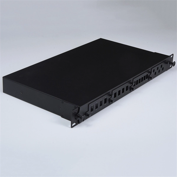
Please view our full RLH price list and contact us at info@fiberopticlink. com if you have any questions or special project needs. A Fiber Optic Patch Panel, also known as an Optical Distribution Frame (ODF) or fiber termination enclosure, is a centralized hardware unit designed to manage, protect, and organize fiber optic cable connections. In an era where data speeds and network reliability are non-negotiable, the patch. fiber optic patch panel, odf, optical distribution frame, fiber distribution panel, rack mount fiber patch panel, wall mount odf, fiber termination box, 1u fiber patch panel, 24 port fiber patch panel, 48 port fiber patch panel, outdoor fiber patch panel, fiber optic odf, sliding patch panel The. Q1: What is the difference between an ODF and a patch panel? An ODF is the entire frame or cabinet managing fiber connections, while a patch panel is a modular unit inside the ODF for cross-connecting fibers. Q2: How many fibers can an ODF handle? It depends on the ODF type; rack-mount units can. ODF is used in the terminal access link of FTTH system. It is a device that splices, distributes, and splits optical fibers and provides protection and management of optical fibers. Belden offers several Fiber Patching Systems. Full patching platforms include FX ECX for LAN environments, FX UHD for high-density fiber channels and the DCX System used primarily in data centers where high amounts of fiber connections and density are the key requirements, as in optical.
[PDF]
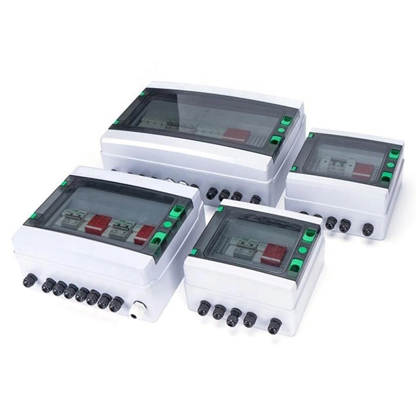
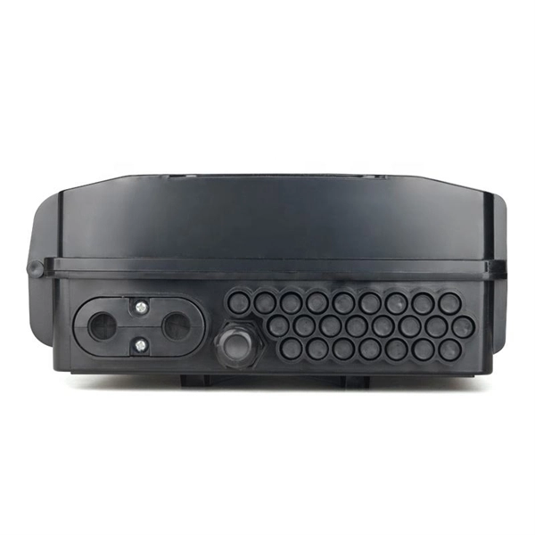
Every temporary power distribution box has several important components that work together to deliver safe, efficient power: These boxes use either 120/240 VAC single-phase or 120/208 or 277/480 VAC three-phase power sources. Temporary power distribution boxes are a budget-friendly way to supply electricity to a remote area. You can use them to power electrical equipment, lighting systems and more. Compared to other temporary power solutions, a power distribution box provides utility, safety and efficiency at an. Temporary power distribution boxes provide a safer way to manage power while keeping your workspace tidy. These versatile units work great for construction sites, entertainment events, and disaster recovery operations. Modern solutions rely on portable. Whether you need an industrial portable power station, a complete jobsite power station, or help managing temporary wiring and distribution, this will help you stay compliant with all the necessary requirements. Getting the selection wrong means more than inconvenience—it can mean shutdowns, damaged machinery, or worse.
[PDF]
Locate the breaker panel, which looks like a large metal box mounted on the wall. Open the panel and look for a switch that's facing the opposite direction from the others. Turn the switch to “Off” and then “On. ” Contact an electrician if your breaker keeps tripping. Yes, in most cases, you can safely turn on a circuit breaker yourself, provided it has merely tripped due to an overload or a minor fault. However, if a breaker repeatedly trips or if you suspect a more serious electrical issue, it's crucial to consult a qualified electrician. Dealing with a. This wikiHow article will teach you how to safely find and flip a tripped breaker, restoring your power. Turn the switch to. This guide's handy whether you're looking at a circuit breaker for the first time or an electrical veteran looking for a better way to explain what to do if the breaker trips. Why Do Breakers Trip? Circuit breakers trip when there's too much current (aka “ overcurrent “) on the circuit, and it. To reset a tripped breaker, switch it entirely OFF first, then back to the ON position. You don't need to turn off the main power to reset individual breakers. Continuously identify and. Mr. Electric recommends these steps to restore power safely when your circuit breaker trips. Turn off and unplug devices on the affected circuit.
[PDF]

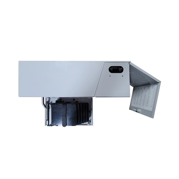
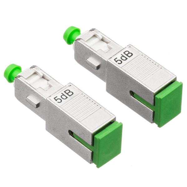
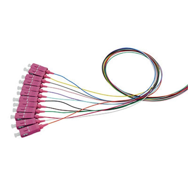
If you are ever in need of checking your ONT, this video will show you how to do so and what it is you are looking for. Always remember to securely close the box afterwards to prevent any damage to the facilities inside. more. A fiber termination box is the standard instrument used in fiber optic networks to connect, secure, and protect optical fibers at the terminating point. It functions as a junction between the incoming fiber cable and the outgoing customer-side fiber cable, where one fiber can be spliced, patched. Open the Fiber optic terminal box. Check and prepare installation tools and accessories. Prepare the cable according to the design. An ONT, or Optical Network Terminal, is the box where your fiber internet connection enters your home to power your fiber network. Your ONT is typically located in your garage, basement or outside your home within a few feet of your home's power box. It serves as a termination point for optical fibers, providing a secure and organized space for connecting and managing fiber optic cables. A fiber pigtail is a specific hardware connection used for cable termination. Proper installation and maintenance of FTBs are essential to ensure the reliability and performance of the network infrastructure.
[PDF]
In this video we show you how to dismantle a concrete telecommunications tower with a crane truck. Every health and safety measures at work were strictly comp. PTTG has experienced crews available to help when owners determine they no longer need their tanks, towers, or other structures and require them to be dismantled and removed, including scrap disposal and site cleanup. On occasion, tanks or towers cease to function or become too old to maintain. This can include towers, batteries, internal equipment, hazardous material, and communication shelter removal. We handle each project with safety and sticking to a budget in mind. Cellular tower demolition jobs can be trickier than most jobs. Legalities of what third parties have access to the site can cause issues–issues we will take care of. Our experienced team handles all aspects of decommissioning, including: • Mount & Antenna Removal – Dismantling old equipment with precision. • Microwave Decommissioning – Safely uninstalling.
[PDF]
In this guide, I'm excited to share with you 15 creative and surprisingly simple ways to transform your ugly electrical box from an eyesore into a part of your home you might actually want to show off. There are actually a whole host of creative and, more importantly, stylish ways to conceal your breaker box or electrical panel without blocking access or impeding functionality. But before you get started, make sure you double-check with an electrician and your local codes. Some electrical codes. Either way, here are unique electrical panel cover ideas to give you some inspiration. Don't let an ugly gray metal electrical panel ruin your decor! Check out these creative solutions for covering one in any room (removable, of course). Our editors and experts handpick every product we feature. We may earn a commission from your purchases. Which is exactly where I was struggling, we have an electrical panel directly in our dining room (small space problems). These fellow bloggers turned their electric panel doors from eyesores into focal points and pieces of art.
[PDF]

In this guide, I'll walk you through everything you need to know about choosing the right cable trays for your cables. Whether you're dealing with power cables, control cables, or communication cables, I'll break it down step by step. A 50 mm cable tray is used to organize and protect cable routes in industrial, commercial, and infrastructure facilities. This compact solution is suitable for power distribution lines, low-current systems, and engineering communications. Mirankul Group manufactures cable trays in Uzbekistan. Accessories for cable systems include a variety of different components necessary for the proper functioning of cable routes. They provide a structured and secure pathway for cables, ensuring organized installation and easy maintenance. Cable Trays are important for ensuring the protection of the wiring system and supporting insulated electric cables used for distribution and communication. Brilltech Engineers Pvt. Understand Your Cable Tray Requirements Before selecting a cable tray, consider the following key factors:. Selecting cable trays can feel overwhelming, especially with so many options available. But don't worry—I've got you covered.
[PDF]
