
Cable Trays* — Max two 24 in. (610 mm) wide by max 6 in. (151 mm) deep open-ladder cable tray with channel-shaped side rails formed of 0. 54 mm) thick aluminum or min 0. In practice, cable tray dimensions are a system of interrelated measurements —width, depth, length, and material thickness—that directly affect cable fill compliance, heat dissipation, structural loading, and long-term expandability. From an engineering standpoint, cable tray dimensions are not. Perforated Cable Tray System expertly constructed from high-grade stainless steel, offering exceptional durability and resistance to corrosion. With side height 100mm. A properly designed and installed cable tray system will provide. Studs — Wall framing to consist of wood studs or channel shaped steel studs. Wood studs to consist of nom 2 by 4 in. Additional studs shall be used to completely frame. Best Size: Here, deep trays (75mm to 150mm) are used since power cables are typically thick and heavy. Data cables, such as your Wi-Fi or computer ones, are extremely sensitive. They do not get hot; however, they do not like to hang or sag. In case a data cable folds in an excessive manner, the. ect the minimum bend ra-dius for cables as they exit the bottom of the cable tray. A rung spacing of 6 to 9 inches (150 to 230 mm) is preferable when the cable tray cont d for instrumentation and control applications that require additional protec eferred to support and protect numerous small.
[PDF]

Step-by-step guide on connecting an inverter to your distribution board for uninterrupted power supply. The process begins with turning off the main power supply to ensure safety. Next, choose an inverter with a suitable capacity to handle your power needs, ensuring it matches the. In this article, you will find information about connecting inverter to distribution box: essential safety tips, step-by-step guidance, and common mistakes that often lead to inverter failure, so that you can avoid them. Last Updated on September 17, 2025 by June The most extensive use of inverter. Connecting an inverter to a distribution board allows you to harness stored energy from batteries or solar panels for powering electrical devices in your home. This setup provides backup power during outages and can also contribute to energy savings by utilizing renewable energy sources. This guide. In this video, we'll guide you through the process of wiring a UPS (Uninterruptible Power Supply) or inverter for your home or office. By following a few simple steps, you can easily learn how to connect an inverter DB wiring diagram. Connecting an inverter DB wiring. Scroll to the bottom of any page to find a sun or moon icon to turn dark mode on or off! I'm not an electrician and do not want to screw this up. What type of wiring do I need to connect the inverter to the distribution box? I have a 1*60A 4*20A FL+LS distribution box with a Sungold Power 5000W 48V.
[PDF]

Check the electrical load and ensure that the sensors do not exceed the 10 Amp maximum. Check each wire for damage that may lead to a short. Check the tightness of electrical connections along the power. Issue: Frequent tripping of circuit breakers is one of the most common issues in distribution boards. It can occur due to overloaded circuits, short circuits, or ground faults. Solution: Identify the Cause: Check if the breaker is tripping due to overloading. Internal Inspection Open the distribution box and check for dust and debris accumulation. Inspect circuit breakers for proper operation. Ensure all connections are tight and secure. Each circuit breaker protects a specific circuit in your home, preventing excessive current from damaging wiring and. MDB is panel under power distribution system which consists of a fuse, circuit breakers and ground leakage protection units. Where electrical energy is taken from a transformer or an upstream panel to distribute electrical power to numerous individual circuits or consumer points. Various types of panels exist in every electrical.
[PDF]

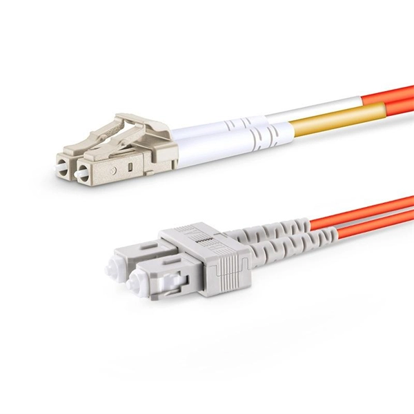
This is a simple video showing how to install a 850nm fiber optic link using SFP transceivers between 2 10 Gigabit backbone switches. Covers transceiver inst. As a leading provider of fiber optic solutions, Weunion offers a wide range of SFP-compatible products, including optical transceivers, DAC/AOC cables, LC patch cords, and MPO/MTP assemblies. This guide explores the essentials of SFP connectivity, installation best practices, and how Weunion's. These transceiver modules are hot-swappable input/output (I/O) devices that plug into 100BASE, 1000BASE and 10GBASE ports (for SFP+), which connect the module port with the fiber-optic or copper network. This document contains these sections: The SFP transceiver modules are hot-pluggable I/O. An optical module is an optoelectronic conversion device that transmits data by converting electrical signals into optical signals. Common types of optical modules include SFP, SFP+, SFP28, QSFP, QSFP28, etc. Different types of optical modules have different performance parameters such as speed. The 1310 nm WWDM solution, 10GBASE-LX4, requires the use of a mode-conditioning patch cord on multimode fiber to achieve its specified range of operating distances. more Audio tracks for some languages were automatically generated. Learn more This is a simple. One of the most widely deployed optical solutions for short-distance 10G links is the multimode SFP+ transceiver, commonly referred to as a 10GBASE-SR module.
[PDF]

While optical power meters are the primary power measurement instrument, optical loss test sets (OLTSs) and optical time domain reflectometers (OTDRs) also measure power in testing loss. TIA standard test FOTP-95 covers the measurement of optical power. This measurement is the basis for loss measurements as well as the power from a source or presented at a receiver. Typically both transmitters and receivers have receptacles for fiber optic connectors, so measuring the. You need a power meter to measure power in a fiber optic system; most power meters come with a screw-on-adapter that matches the connector being tested and a little aid from the network electronics to turn on the transmitter. During the measurement of power, the meter must be set to the proper. Fluke Networks sets the standard in network testing with its advanced range of fiber optic power meters and fault locators, designed to ensure the highest precision in fiber optic meter readings and power evaluations. This is measured in decibels (dB). Splitters, fusion splices, connectors and. To use a power meter for fiber optic testing, always clean connectors first with lint-free wipes or click-to-clean tools. Select the correct wavelength and set your reference. Consistent procedures ensure accuracy.
[PDF]

The first thing you should do is locate the fiber optic cable that comes from the service provider. Once inserted, make sure it is securely. However, setting up a fiber optic connection to your router can seem daunting if you're unfamiliar with the process. Why Use Fiber Optic Internet? Before diving into the setup, let's quickly. Ensure your fiber optic router has an available WAN (Wide Area Network) or Ethernet port for the fiber optic modem. It's thin, flexible, and usually comes with connectors on both ends. Power Cables: Get power cables for both the. The fiber optic cable does not plug directly into a standard home router because the signal type must be translated. The fiber line terminates at the Optical Network Terminal (ONT), which is typically supplied and installed by the internet service provider. This specialized equipment serves as the. The process to connect fiber optic cable to router requires careful attention to detail, but I'll walk you through every critical step with the precision and clarity you deserve. Here's a step-by-step guide to help you through it. Understand the Basics Before diving in, familiarize yourself with the components involved:. Follow along as we take you through the step-by-step process of installing fiber internet! From preparing the site to connecting the final cables, we'll show you what goes into bringing high-speed internet to your doorstep. Whether you're a tech enthusiast or just curious about how it all w.
[PDF]
We're talking anywhere from $45 for a small residential unit to over $6,000 for industrial-grade modules. In this guide, as a professional hollow fiber membrane manufacturer, I'll break down exactly what influences these prices and how to get the best value for your specific. What's the hollow fiber membrane price going to set you back? Here's the deal: Hollow fiber membrane costs vary WILDLY. The Global Hollow Core Fiber Market will grow at a CAGR of 10. 92% from 2025 to 2031, reaching USD 24. Industrial uses and innovation fuel this surge, with the market predicted at USD 11. The pricing dynamics of the hollow core fiber market are influenced by factors. Check each product page for other buying options. Price and other details may vary based on product size and color. Need help?. The price of hollow fibers varies significantly based on material composition, manufacturing process, sustainability, and performance characteristics. Understanding the different types helps buyers make informed decisions for both commercial and personal applications. Fibers colored during the. Cobetter hollow fiber filters are made of low-binding modified polyethersulfone membranes (m-PES) that deliver excellent filtration performance. The low shear stress makes it ideal for the processes of cell harvest, clarification, diafiltration and concentration where gentle and fast separation is.
[PDF]

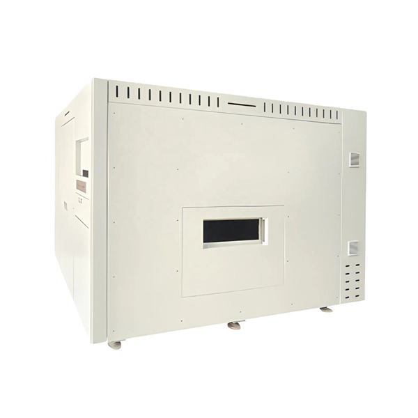
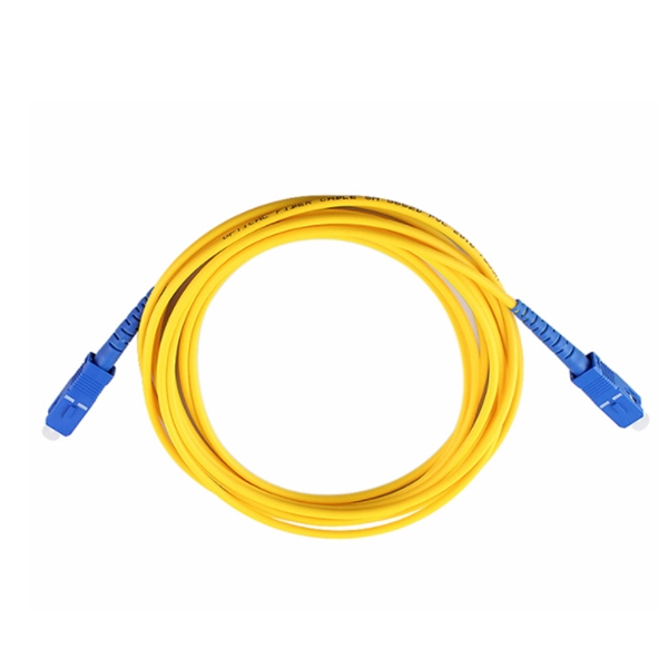
The compact 1 port ftth fiber termination box can hold 2 cores splicing, termination and coil up to 30 meters long for cable management in FTTH network. The 1 port fiber termination box is available for fiber optic cable coiling, it is great to connect optical cable and pigtail and protect fiber splices from damage. It is small, lightweight, and offers the function of fiber splicing, storage, and termination, mainly used in residential buildings. The maximum distance for single mode fiber optic cable can extend up to several hundred kilometers, making it ideal for long distance data transmission. One type of single mode fiber is known as “G. 652,” which is commonly used in telecommunications networks. Here are some general guidelines: 1. The shorter distance accounts for the. A fiber optic distribution box (FDB) is a protective enclosure for managing fiber optic cables. It organizes connections, splices fibers, and distributes signals in networks like FTTH (Fiber-to-the-Home) or FTTB (Fiber-to-the-Building). It acts as a central point for terminating, splicing, and distributing these cables, providing necessary protection and. The Fiber Optic Association, Inc. (FOA) was founded in 1995 to help develop the workforce to build the fiber optic networks to support a rapid expansion in communications and the Internet. The charter of the FOA was to promote professionalism in fiber optics through education, certification, and.
[PDF]

Non-polarizing beamsplitters are specified by their splitting ratio, i. the ratio of P-polarized light to. A beam splitter or beamsplitter is an optical device that splits a beam of light into a transmitted and a reflected beam. It is a crucial part of many optical experimental and measurement systems, such as interferometers, also finding widespread application in fibre optic telecommunications. a laser beam) into two (or sometimes more) beams, which may or may not have the same optical power (radiant flux). Different types of beam splitters exist, as described in the. The collimated incident laser beam passes through the beam splitter, and the output beam is emitted at a specific separation angle on the output beam array. The following figure is an introduction to the basic settings of a beam splitter. Circular beamsplitters, plate beamsplitters and cube beamsplitters can be purchased for polarizing or non polarizing beamsplitting. Beamsplitters are optical components used to split incident light at a designated ratio into two separate beams.
[PDF]

Learn how to install a distribution box safely and correctly. Covers wiring, placement, standards, and expert tips for a compliant setup. It takes the incoming power and safely distributes it to different. In this video, we'll walk you through the process of wiring a home distribution box with a detailed connection diagram. more Welcome to our channel! In this video. Whether you are an electrical contractor or a construction brigade, knowing how to properly and safely install distribution boxes is the basis of ensuring the safe operation of the entire system. It serves as a central hub for distributing electricity throughout a building, ensuring that power is delivered safely and efficiently to all the required locations. In modern electrical systems, cable distribution boxes (also known as electrical distribution boxes or distribution boxes) play a crucial role as the key hub for managing, distributing, and protecting circuits. Whether it is residential buildings, commercial facilities or industrial sites, the. In this guide, we will break down the key elements involved in connecting the main power supply to your home, providing a clear path for a successful setup. We will focus on the critical parts of the system, from basic components to step-by-step assembly procedures. Whether you are looking to.
[PDF]
Den här guiden går igenom allt du behöver känna till när du vill koppla din egen router till fiber, vilka alternativ som finns, vilka inställningar som krävs och hur du felsöker om något inte fungerar som det ska. However, setting up a fiber optic connection to your router can seem daunting if you're unfamiliar with the process. In this guide, we'll walk you through how to connect a fiber optic cable to a router safely and efficiently. Why Use Fiber Optic Internet? Before diving into the setup, let's quickly. Setting up a fiber internet connection requires understanding key hardware components and following a specific connection sequence to establish your home network. This comprehensive guide combines industry standards with field-tested practices to ensure you achieve a rock-solid.
[PDF]

In the 2020 NEC ®, no more than 18 inches of cable length is allowed between the cable entry to the box and the closest cable support (see image). Below is a preview of the NEC®. ORG for the complete code section. The previous code language could technically allow an unlimited length of coiled up NM cable inside the wall as long as it was secured within 12 inches of the box. This code is based upon the type of box, wires, wire sizes, wire clamps and conduit fittings. Adjustments are made for the ground wire as you will see in the. Calculate and select the right number and spacing of cables for junction boxes using NEC guidelines to ensure safe, code-compliant electrical installations. This step keeps your project safe and. According to the National Electrical Code (NEC), the conductor must be long enough to extend outside the box's opening. This length allows enough room to connect, splice, or terminate wires without strain or damage. If wires are too short, they may fail inspection or create hazards during. The length of wire left inside an electrical box is a matter of strict compliance, safety, and functionality. Having the correct amount of slack ensures that future maintenance, repairs, or device replacements can be performed without difficulty. Proper electrical box fill calculations are critical for code compliance and safety in both residential and commercial installations.
[PDF]
In this article, we will guide you through the step-by-step process of opening an electrical box safely and effectively. We will also highlight the necessary tools and materials you will need to complete the task. The electrical service panel, commonly known as the breaker box, acts as the central distribution hub for all electrical power entering a home. This metal enclosure receives high-voltage current from the utility company and safely divides it into various circuits that supply power to lights. So, before we dive into the discussion, here's a list of tools that you must have. Electric Drill/Screwdriver 2. Personal Protective Equipment Step 1. Clear your working area Step 2. Estimate the cover's weight Step 4. It is responsible for controlling and distributing the electrical current throughout your house, ensuring the safety and efficiency of your electrical appliances and devices. This article details the process of installing them, which helps you comprehend distribution boxes. An electrical panel box, also known as a breaker box or a distribution board, is a crucial component of any electrical system. Whether you're a seasoned DIY enthusiast or simply looking to understand the procedure, this guide will provide a clear roadmap to ensure a smooth and safe transition. Let's embark on this.
[PDF]
Dispersion of an optical fiber directly affects the bandwidth and distance capability of the fiber optic link and reduces its efficiency. The higher the dispersion, the lower the potential data rate and transmission distance. Fiber optic cable transmission distance is determined by two primary physical factors that affect signal quality as light travels through the fiber medium. The greater the distance, the greater. With amplifiers, such as Erbium-doped fiber amplifiers (EDFAs), the distance can be extended to 600 miles or more, and even further with additional amplifiers for long-haul applications. In this guide, we'll explore how fiber optic cables function, the maximum distances for different types of fiber optics, and tips for. Fiber optics transmits information by sending light signals through thin strands of glass. While this technology offers higher speeds and longer distances than traditional copper wiring, physical limitations impose distance constraints. Light pulses degrade as they travel over long spans, primarily. The maximum distance a fiber optic cable can transmit data reliably is influenced by several key factors, primarily the inherent properties of light and the physical characteristics of the fiber itself. Understanding these limitations is essential for designing efficient and robust internet.
[PDF]
In this video we show you how to dismantle a concrete telecommunications tower with a crane truck. Every health and safety measures at work were strictly comp. PTTG has experienced crews available to help when owners determine they no longer need their tanks, towers, or other structures and require them to be dismantled and removed, including scrap disposal and site cleanup. On occasion, tanks or towers cease to function or become too old to maintain. This can include towers, batteries, internal equipment, hazardous material, and communication shelter removal. We handle each project with safety and sticking to a budget in mind. Cellular tower demolition jobs can be trickier than most jobs. Legalities of what third parties have access to the site can cause issues–issues we will take care of. Our experienced team handles all aspects of decommissioning, including: • Mount & Antenna Removal – Dismantling old equipment with precision. • Microwave Decommissioning – Safely uninstalling.
[PDF]

