Its primary purpose is to ensure safe and efficient power distribution while providing protection via fuses or circuit breakers against overloads and short circuits. Distribution boxes are built with durable materials, typically metal or high-grade plastic, designed to endure. Most distribution boxes contain circuit breakers or fuses that function as protective barriers for the connected wiring and electrical devices. These safety components monitor the electrical flow continuously. When electrical problems occur—such as short circuits or excessive power draw—the circuit. Its primary role is to ensure safety, control, and organization. Let's break down its core functions. Centralized Control and Distribution The main function of a Distribution Box is to act as a central hub. The single, thick cable bringing power from the utility company enters this box. Inside. A low voltage distribution box safely manages and protects electrical circuits, ensuring reliable power distribution and enhanced safety in any building. It is commonly used in homes, offices, and industrial settings to control and protect electrical circuits. It helps organize, protect, and control electrical connections in residential, commercial, and industrial electrical systems.
[PDF]
5 inch CETC Optic fiber OTDR AV6418,Fiber optic test tester,1310/1550nm,45/43dB large dynamic range,built in Optic power meter and VFL Description: AV6418 OTDR mainly used to measure the physical characteristics of optical fiber under test,such as the length,the transmission loss. 6. 5-inch display offers an event blind zone of 1 m and operates with locater This product is already in your quote request list. Measuring Measuring loss (dB) in the range between 800nm – 1700nm. Power AC/DC adapter; Input:100V~240V, 50/60Hz. Polarization extinction ratio (PER) is a measure of the degree to which light is confined in a principal linear polarization mode. It is defined as the ratio of the power in the principal polarization mode to the power in the orthogonal polarization mode after propagation through a device or. The ERM2xx Extinction Ratio Meters measure the polarization extinction ratio (PER) and the polarization angle of polarization-maintaining (PM) fibers. It features unmatched low cost, all wavelength options, a large dynamic range, and high resolution. The design adds a rotary polarizer to an optical power meter.
[PDF]
Key techniques include using bonding agents, saw-cutting, re-pouring concrete, mechanical connectors, and epoxy injection. Conventional methods like epoxy grout injection can address cracks effectively. Learn how to prep and bond a next-day concrete pour to repair a cold joint. This guide walks through practical surface prep, bonding methods, and timing so you can create a strong, durable joint. You'll gain actionable, plain-language steps and tips you can apply on real job sites. Identify cold. A cold joint is a common imperfection in concrete construction, occurring when fresh concrete is poured next to a section that has already begun the setting process. This discontinuity prevents the two pours from chemically integrating into a single monolithic unit, creating a weak plane within the. A cold joint in concrete is an area or surface with a structural discontinuity caused by the delayed concrete pouring between two layers of concrete. This issue compromises the structural integrity and durability of the concrete. This transition from a plastic or fluid state to a semi-solid state creates a discontinuity.
[PDF]

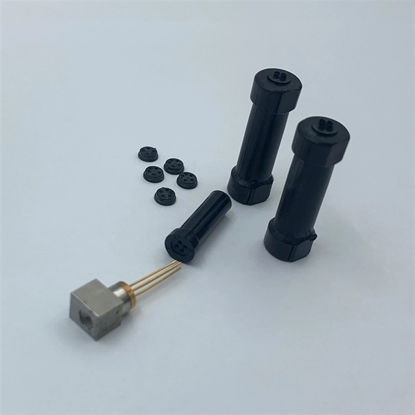
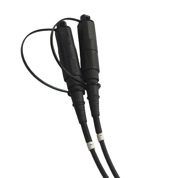
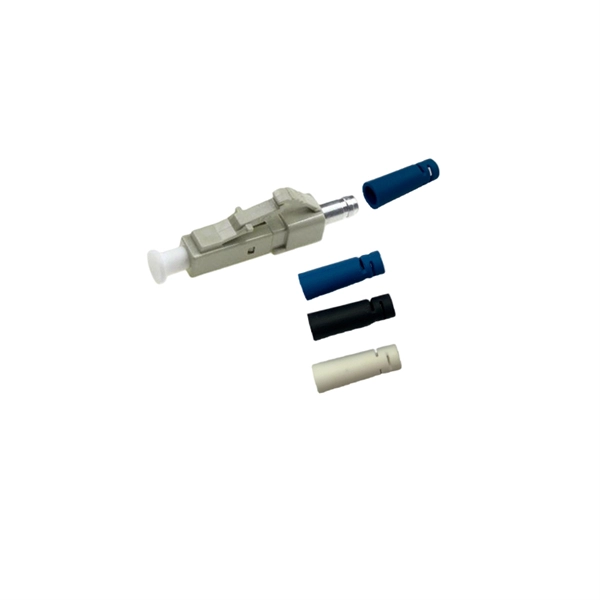
While most pigtails are single-fiber, multi-fiber options exist: Single-fiber: The most common (LC, SC, FC). Multi-fiber: 2, 4, 6, 12, 24, 48, or 72 fibers. Multi-fiber pigtails often come in ribbon format for splicing into high-count cables. Traditional Fusion Splice-On Connectors with pigtails provide factory-polished performance with field-termination convenience within harsh environments. Mass fusion splicing can fuse up to all 12 fibers in one ribbon at once. Mass Fusion Pigtails come with all 12 fibers terminated and a ribbonized. By fiber type, there are single-mode fiber optic pigtail and multimode fiber optic pigtail. And by fiber count, 6 fibers, 12 fibers optic pigtails can be found in the market. Fiber pigtails are used in an estimated 99% of single-mode fiber applications worldwide. Despite this ubiquity, they remain a source of confusion for procurement teams and junior installers alike—especially when it comes to connector type selection, polish type, and the tradeoffs between mechanical. Fiber optic pigtails can be divided into single-mode and multimode fibers. Conversely, multimode fiber pigtails, usually orange, use a 62. 5m to 2m—that has a factory-terminated connector on one end and bare fiber on the other end. The connector end is polished and tested under factory conditions, ensuring low insertion loss and high return loss.
[PDF]

Not all splitters are created equal. Here are the main types you'll encounter: The "1×N" notation indicates one input fiber and N output fibers. A 1×2 splitter divides the signal into two outputs, while a 1×8 splitter divides it into eight. The more splits, the. By dividing a single optical signal from a central Optical Line Terminal (OLT) into multiple outputs for Optical Network Terminals (ONTs) at users' homes, splitters eliminate the need for dedicated fibers to each residence—slashing infrastructure costs while scaling network reach. This guide. A fiber-optic splitter, also known as a beam splitter, is based on a quartz substrate of an integrated waveguide optical power distribution device, similar to a coaxial cable transmission system. The optical network system uses an optical signal coupled to the branch distribution. The fiber optic. Optical couplers can split or join signals in fibers. You can connect many users to one port with 1:n or 2:n splitters. These devices work both ways, which helps strong network communication. In a Passive Optical Network (PON), a single optical fiber carries massive amounts of data using light. They are named by the number of inputs and outputs, so a splitter with one input and 2 outputs is a 1X2, and a PON splitter with one input and 32 outputs is a 1X32.
[PDF]

Optical fiber is composed of three elements – the core, the cladding and the coating. These elements carry data by way of infrared light, thus propagating signal through the fiber. The core is at the center of the optical fiber and provides a pathway for light to travel. A TOSLINK optical fiber cable with a clear jacket. These cables are used mainly for digital audio connections between devices. A fiber-optic cable, also known as an optical-fiber cable, is an assembly similar to an electrical cable but containing one or more optical fibers that are used to carry. This is the first in a series of five courses about fiber optic cable systems. The first course, Fiber Optics I –Theory, is an overview of the technology of fiber optic. An optical fiber cable is a complex structure designed to protect fragile glass fibers that transmit digital data using light signals. This advanced cabling solution allows fast, secure data transfer and telecom over long distances. When searching for a fiber optic cable, we need to pay attention not only to the connectors, such as SC to ST fiber cable, LC to SC fiber patch cable, or SC to. This guide explains the structure of fiber optic cables, the most common cable constructions used in the industry, and how to choose the right cable type for indoor networks, outdoor deployments, data centers, and FTTH systems. In multimode fiber, the.
[PDF]
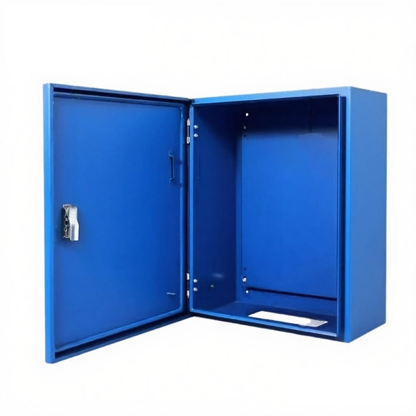
With protective doors, dust-proof 2). Suitable for many types of modules, used in cabling work area subsystem 3). Embedded type surface, easy for installation and removal 4). Available for fiber optic SC simplex or LC duplex and can be used in both surface mounted. 1). This termination box supports 0. 0mm pigtails and 2x3mm indoor drop cables. Discover the Welink FTB-1005: a high-quality 1 Core Fiber Optic Outlet for FTTH. RoHS certified, compact, durable, and easy to install. Compact Design: Space-saving footprint (86x86mm) ideal for residential and office wall mounting. Splice Protection: Integrated tray securely holds fusion. FTTH Terminal box is a compact fiber terminal for use at the final fiber termination point in the customer premises. It provides mechanical protection and managed fiber control in an attractive format suitable for use inside customer premises, A variety of possible fiber termination techniques are. 1 Core Fiber Optic Desk Terminal Box for SC, FC Adapter, Patch Cord or Pigtail Description: 1). It provides a secure and convenient location for fiber optic splicing, connecting the drop cable and the passive optical equipment of the optical network. protection and management for the FTTx network building. Features: Scope of application 3. Specification: Applications: 1 Core Fiber Optic Terminal Box is used as a termination point for the feeder cable to connect with drop cable in FTTx communication network.
[PDF]