The 6 terminal junction box wiring diagram provides a visual representation of how the various wires and connections should be made within the box. It shows the layout and arrangement of the terminals, as well as the color coding and labeling of the wires. Hey, in this article we are going to see the Single Phase Distribution Box Wiring Diagram and Connection Procedure. A distribution board or distribution box is where the main power supply is distributed to multiple loads. It provides a quick and easy reference guide to understanding the meaning behind each symbol. These symbols can represent different electrical components, such as switches, resistors. This technical article aims to take you on a journey through the fundamental terminals and other connecting elements of wiring diagrams and electrical schematics and to delve into the minute intricacies of the components that form them. From the familiar male and female terminals that form the. An electrical panel box, also known as a breaker box or a distribution board, is a crucial component of any electrical system. Whether you're an electrician or a DIY enthusiast, this guide will help you understand the basics of home electrical distribution. more Welcome to our. The Engineering Base terminal block diagram is a special template showing information about terminal blocks, terminals and their accessories. There are two methods for creating a terminal block.
[PDF]

Simple 3-phase distribution board wiring diagram for home use, showing safe connection of power supply, breakers, neutral, and earth for residential electrical systems. Hey, in this article we are going to see the Three (3) Phase Distribution Board Wiring Diagram and Connection Procedure. The three-phase distribution board is used to distribute power to the three-phase loads and circuits such as three-phase motors, three-phase machinery, three-phase to. A distribution board, also known as a DB box, is like the central hub of an electrical system. It contains multiple circuit breakers and connects various electrical circuits to ensure the safe flow of electricity throughout the building. Unlike single-phase systems, where power is distributed using. When it comes to understanding the basics of electricity and wiring, a wiring diagram of a three phase distribution board is indispensable. This diagram shows how electricity is distributed in a home or building and helps you identify which connections should be made when constructing, modifying or. Welcome to our channel! In this video, we'll walk you through the process of wiring a home distribution box with a detailed connection diagram. Whether you're an electrician or a DIY enthusiast, this guide will help you understand the basics of home electrical distribution. These setups typically provide 240V for most applications, but it's crucial to follow the proper configuration to prevent hazards.
[PDF]
Free electrical calculators for wire sizing, voltage drop, load calculations, conduit fill & power factor. NEC compliant tools for electricians & engineers. In this guide, we'll break down everything you need to know to install a distribution box correctly and confidently. Choose the right box based on environment (indoor/outdoor), load capacity, and durability. Check for proper IP/NEMA ratings and material quality. Ensure safe placement: install in. Professional electrical wire sizing tool based on National Electrical Code (NEC) standards. Calculate proper wire gauge, voltage drop, and ampacity for safe electrical installations. Input your electrical parameters to get accurate wire size. Pro Insight: A well-planned distribution box feels like a silent partner—you only notice it when something's wrong. Our goal? Make sure you never notice it. Before we dive into calculations, let's get familiar with a few essentials: 1. Create accurate bids and win more projects with automated formulas. The sizing requirements for pull boxes, junction boxes, handhole enclosures, and conduit bodies exist to prevent conductor insulation damage. Those requirements are in 314. 28, and they apply to all conductors 4 AWG and larger (Fig. To illustrate how these requirements prevent conductor. Estimate wire ampacity with derating factors for temperature and conduit fill. Reference tool based on NEC guidelines. It is NOT a substitute for professional.
[PDF]

In the following tutorial, we will show how to wire 120V single-phase and 240V split-phase circuit breakers and loads inside a residential main panel. The figure below shows a typical breaker panel used for 120V and 240V circuits. Messy distribution boxes are dangerous and very hard to fix. You will learn to build a safe, efficient, and professional electrical system today. Circuit breaker wiring configurations involve organizing main switches, busbars. A breaker box, also known as a circuit breaker panel, is an essential component of any electrical system. It is responsible for distributing electricity throughout a building, ensuring that each circuit receives the proper amount of power. To understand how a breaker box works, it is helpful to. Each circuit is protected by a circuit breaker, a safety device that automatically shuts off power if it detects an overload or a fault. If you're looking to replace an old fuse box replacement or upgrade your home's power capacity, you'll be dealing with the load center or service panel. The distinction between 1P and 2P circuit breakers plays a pivotal role in determining the appropriate protection level for various circuits. When installing or troubleshooting a power distribution system, understanding how to correctly connect the main electrical supply to the control panel is crucial.
[PDF]
Ensure safe placement: install in dry, accessible areas with good ventilation and at appropriate height (typically ~1. Practice good wiring: secure grounding, neat cable management, proper insulation, and correct wire gauge and breaker size. The term “four wires” refers to three live wires and one neutral wire, designated as A|B|C|N|, with N representing the ground wire. The three live wires should be connected to the upper entry of the main switch in the explosion-proof distribution box, and the neutral wire should be directly. Learn how to wire a distribution box step by step! This video shows real on-site footage of electrical installation, demonstrating safe and standardized wiring methods used by professionals. This ensures compliance with NEC and simplifies troubleshooting. Include protection devices like breakers, fuses, and. Prevention of Electrical Hazards: Proper wiring ensures that electrical currents flow smoothly and safely through the circuits, minimizing the risk of electrocution and electrical accidents. Faulty wiring can result in electric shocks and even be life-threatening. Efficient Power Distribution: The. ormal operation due to poor manufacture quality. A paid repair will be provided if the warranty period expires. For any damage due to one of the following situations, a paid repair duct, please dispose the pro ype, a “R” is added after the Specification. For single row 20, and circuit 24, fter.
[PDF]
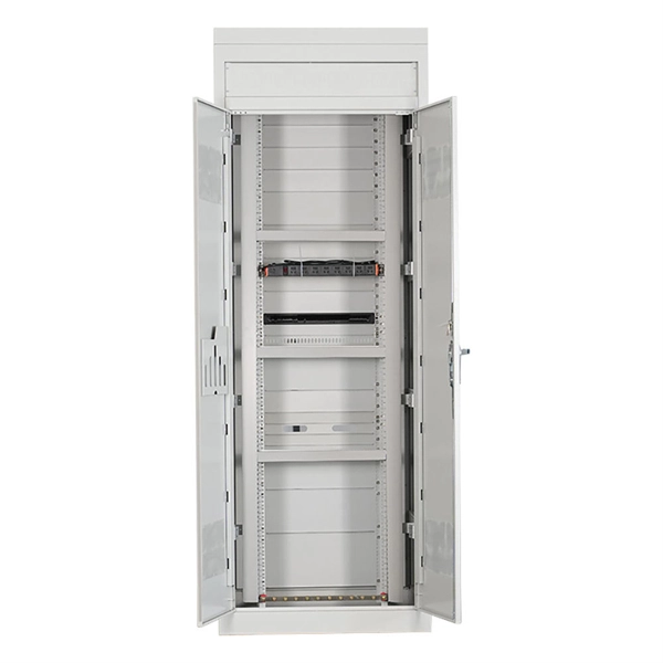
Welcome to our channel! In this video, we'll walk you through the process of wiring a home distribution box with a detailed connection diagram. It serves as a central hub for distributing electricity throughout a building, ensuring that power is delivered safely and efficiently to all the required locations. And all the switching and protective devices are installed in the. Distribution Board or DB is an electricity supply system or a common enclosure that distributes the electrical power feed into subcircuits. It includes isolator, RCCB (Residual current circuit breaker) or RCD (Residual-current device) devices, protective fuses or MCB's (Miniature Circuit Breaker). That's why having a clear, detailed diagram of your home's distribution board wiring is essential. A distribution board (also known as a service panel or breaker box) is a centralized collection of circuit breakers, fuses, and/or relays used to control and protect the wiring in a home.
[PDF]
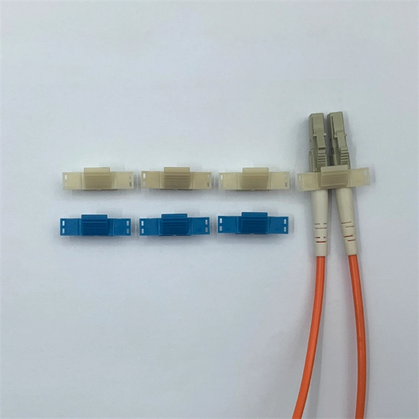
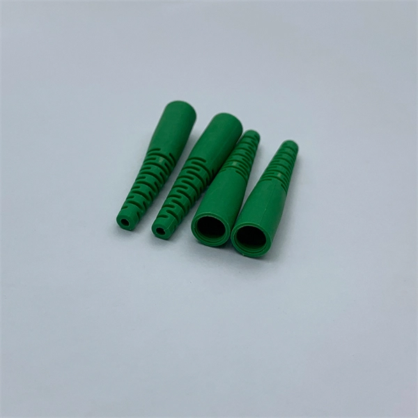
The 8 Port Fiber Access Terminal (FAT) is designed to connect feeder cables to subscriber drop cables for FTTH last-mile fiber connectivity; it can achieve direct or branch and terminal connection in FTTH or FTTB projects. FTB-SC8-WOPA type fiber optic terminal box is designed for FTTx application, which is cable to meet at least 8 users requirements. It can help splicing, splitting, storage and management with suitable space. Simple with light weight in design, special snap clip close system coinvent for user. ORCA® terminal optic box it is the best solution for indoor optical cable distribution or termination. The plastic case it is very light for a simple use. The FOTB fit the SC Simplex adapter (on request with ST and FC adapter). It is possible to buy the unloaded version (w/o Adapter) or the. Maximum capacity: 8 SC simplex, 8 LC duplex. The 8 port Fiber Distribution Box is sturdy in structure, lightweight in size, and easy to install. Built with high-density configurations and rugged materials, this MST box is perfect for installations in harsh environments like 4G/5G. The wall-mounted optic fibre termination box allows for easy organization of optic fibre cables (up to 4 fibres, depending on the installed adapters.
[PDF]
See a sample diagram and download it in different formats. Electrical enclosure sizes are not universal, but most manufacturers follow common size families. This guide explains typical wall-mount and floor-standing dimensions, how to read catalog sizes, and how to choose the right enclosure size for your layout. What Are Electrical Box Dimensions? Electrical box dimensions typically refer to: Correct dimensions ensure:. Solid rubber (construction) distribution box suitable for construction and industry according to EN-61439-4. Available from stock. The only one in the Benelux with a Dekra quality mark. Distribution boxes 32 Amp. Explorez notre Guide Complet du RGIE : Schémas Électriques, Conseils de Conformité, Assistance Gratuite pour la Sécurité et la Mise aux Normes des Installations, et Accès Direct aux Électriciens et Agences Agréées. Discover easy access to the Belgian Electrical Regulations resources, structured. Sheet Electrical: Electricity symbols for floor plans (based on Belgium regulations). Learn more about these objects, how they can be added to your Dia toolbox and how you can draw your diagrams with them. Boxes distribute low currents in an area equipped with 1 to 12 RJ 45 sockets. They centralise connections to ensure flexibility and that the installation is up to date. Area boxes can be installed in technical flooring or in false ceilings.
[PDF]
The following wiring diagram shows the installation of a 60A subpanel for both 120V and 240V. You may use the current rating according to the system requirement i. 50A, 60A, 100A, 150A and so on. We have used 60A for illustration purposes only. Click image to enlarge. Primary distribution systems consist of feeders that deliver power from distribution substations to distribution transformers. A feeder usually begins with a feeder breaker at the distribution substation. Many feeders leave substation in a concrete ducts and are routed to a nearby pole. At this. An electrical sub panel, also known as a sub distribution board or sub circuit breaker panel, is a smaller secondary panel connected to the main electrical panel in a building. It serves as an extension of the main electrical panel to distribute power to different areas or circuits within a. secondary unit substation is a close-coupled assembly consisting of enclosed primary high voltage equipment, three-phase power transformers, and enclosed secondary low-voltage equipment. We have used 60A for illustration. Installing a subpanel is best handled by a professional electrician, but if you're curious how it's done, here is a brief overview of how to install a subpanel breaker box. Equipment Identify the location where you're adding a second breaker box. This information will help as you consider a Sub-Panel and its size. Electrical Tips and Be Sure to.
[PDF]

Figure 1 is a diagram of the basic construction of both loose-tube and tight-buffer fiber optic cable. An optical fiber cable is a complex structure designed to protect fragile glass fibers that transmit digital data using light signals. This advanced cabling solution allows fast, secure data transfer and telecom over long distances. Understanding the components within a fiber optic cable enables. A fiber optic cable consists of five basic components: the core, the cladding, the coating, the strengthening fibers, and the cable jacket. When searching for a fiber optic cable, we need to pay attention not only to the connectors, such as SC to ST fiber cable, LC to SC fiber patch cable, or SC to. Optical fibers are circular dielectric wave-guides used to contain and transmit light over short or long distances. They consist of three elements as shown in Figure 1: a central core, cladding and a protective coating. Understanding its internal structure is essential to appreciate how it functions efficiently in various applications, from telecommunications to medical devices. The core is the. 3,260 optical fiber structure illustrations, drawings, stickers and clip-art are available royalty-free for download. Multimode all-media self-supporting fiber optic cable structure isolated on white. More specifically, we can say that it is a waveguide that has the ability.
[PDF]

In this guide, you will learn how to interpret network diagrams like a pro, from symbols and scope to segmentation, dependencies, troubleshooting, and security clues. A rack elevation diagram is a visual representation of the equipment and components contained within a rack in a data center or server room. It provides a clear overview of the physical layout of the rack, including the placement and positioning of servers, switches, storage devices, and other. Learn how to read and interpret network diagrams effectively to troubleshoot, validate security, and plan network changes with confidence. Have you ever opened a network diagram and felt like you were staring at a subway map with no station names? That is a common problem, even for experienced IT. Network cabinet cabling describes the structured connection and arrangement of all IT components in a server rack. The aim is a secure, maintainable and scalable operation of the network environment. The amount. A standard operating procedure, or SOP, is a set of step-by-step instructions compiled by an organization to help workers carry out complex routine operations. Work instructions should be very detailed on "how" to accomplish a specific job, task or assignment. It helps teams understand network architecture, data flow, and dependencies, making it easier to design infrastructure, troubleshoot issues, and plan.
[PDF]
A neat, well-organized subpanel bundles wires to conserve space and improve access. Ideally, wire groups are installed in layers and wires are bent at right angles to buses or breakers. Label short sheathing sections (slugs) to indicate which circuits wires serve. A cluttered or messy junction box can lead to electrical hazards, such as short circuits or difficulty diagnosing issues later on. Whether you're a professional electrician or a DIY. Welcome to this live training session! ⚡ In today's tutorial, I'll be demonstrating how to arrange cables neatly inside a distribution bo. more See what others said about this video while it was live. After all, a well-organized junction box is like a well-organized sock drawer: you might not notice it, but when it's a mess, everyone knows. And let's be honest—nobody wants to dive into a rat's. Whether you're a homeowner or working with a residential electrician in Richmond VA, managing your cables properly makes your space look better, increases safety, and improves functionality. Learning how to keep wires organized not only improves the appearance of your space but also makes your. To ensure the aesthetic appearance of the wiring installation inside the electrical ready board box, the following points can be followed: Grouping and layering: Grouping and layering neutral, live, and ground wires to ensure clear and orderly routing of the lines. Horizontal and vertical: When.
[PDF]
will introduce major upgrades to its Multi-Rail technology platform at ECOC 2025, targeting hyperscale optical transport with new efficiency, scale, and performance enhancements. Coherent Corp. SAXONBURG, PA, September 26, 2025 (GLOBE NEWSWIRE) – Coherent Corp. At the heart of the. SAXONBURG, Pa. At the heart of the. Simultaneously, coherent technology has emerged as the prevailing solution for Data Center Interconnection (DCI) applications, covering distances of 80~120km in the field of data communication. These evolving applications introduce new demands for coherent optical transceiver systems, steering the. Coherent optical module refers to a typically hot-pluggable coherent optical transceiver that uses coherent modulation (BPSK / QPSK / QAM) rather than amplitude modulation (RZ/ NRZ / PAM4) and is typically used in high-bandwidth data communications applications. Optical modules typically have an.
[PDF]

Explore our comprehensive SFP optical module selection guide for 2025. Learn about crucial factors like data rate, distance, fiber type, and compatibility to optimize your network performance and cost-effectiveness. Make informed decisions for your networking needs today!. SFP (Small Form-factor Pluggable) is a compact, hot-pluggable network interface module used to connect network devices (switches, routers, firewalls) to fiber optic or copper cables. They're essential for extending network distances and increasing bandwidth capabilities. Selecting the correct SFP module is not simply a matter of matching connectors. In modern Ethernet networks, choosing the wrong transceiver can result in link failures, speed mismatches, compatibility errors, or unexpected distance limitations. For network engineers, system integrators, and IT. At the core of these advanced networks are bidirectional SFP modules, also known as BiDi SFP transceivers—compact, cost-efficient devices that support high-speed data transmission and reception over a single optical fiber. By using different interfaces and single-mode or multimode fiber depending on the.
[PDF]

This comprehensive guide explores the technical requirements, installation best practices, and protection coordination strategies for MCCB-busbar connections. Messy distribution boxes are dangerous and very hard to fix. This guide shows you how to organize circuit breaker wiring properly. You will learn to build a safe, efficient, and professional electrical system today. Circuit breaker wiring configurations involve organizing main switches, busbars. An electrical panel box, also known as a breaker box or a distribution board, is a crucial component of any electrical system. It serves as a central hub for distributing electricity throughout a building, ensuring that power is delivered safely and efficiently to all the required locations. The distinction between 1P and 2P circuit breakers plays a pivotal role in determining the appropriate protection level for various circuits. Wiring Square D Panel refers to the process of connecting electrical circuits within a Square D panel, which is a type of electrical panel commonly used in residential and commercial buildings. The electrical panel, also known as a distribution board or breaker box, is responsible for distributing. While some homeowners may attempt this, it's highly recommended to hire a qualified, licensed electrician for circuit breaker box wiring. This is a complex and potentially dangerous task that involves working with high voltage electricity. To understand how a breaker box works, it is helpful to.
[PDF]

