
An Optical Splitter, also known as a beam splitter, is a passive optical device that divides a single input optical signal into two or more output signals. Conversely, it can also combine multiple signals into one. Knowing the difference between a splitter and an optical coupler helps you build better networks. You make your network work better when you pick the right device for each job. You can connect many users to one port with 1:n or 2:n splitters. By dividing a single optical signal from a central Optical Line Terminal (OLT) into multiple outputs for Optical Network Terminals (ONTs) at users' homes, splitters eliminate the need for dedicated fibers to each residence—slashing infrastructure costs while scaling network reach. This guide. In a Passive Optical Network (PON), a single optical fiber carries massive amounts of data using light. Signal Input: The fiber splitter receives the optical signal from the upstream network node and enters the splitter through the input fiber. Signal Distribution: Inside the splitter, according to the design structure and different. Splitters are passive optical devices that divide or combine optical signals, and they come in various types, including power splitters, uneven splitters, and wavelength-division multiplexing (WDM) splitters. Each type serves specific applications, enabling efficient use of optical infrastructure.
[PDF]
ODF, also known as optical distribution frame or fiber optic patch panel, is a critical device used in optical communication for managing and distributing optical fibers. It is usually a compact and structured framework composed of a steel shell and internal fiber splice tray as the. This complete guide explores everything you need to know about ODFs — from their structure, types, and key components, to installation best practices and modern design trends. Whether you're building a central office, data center, or FTTx distribution network, understanding the right ODF. An Optical Distribution Frame (ODF) is the central hub for fiber splicing, termination, patching, and cable protection in modern optical networks. Mainly used in the junction point between the optical transport networks and the optical transmission equipment, or bet een the optical fiber access networks and the user cable. It serves as a merging point for the optical fibers, where connections are consolidated and routed, thus minimizing signal attenuation. The ODF includes.
[PDF]
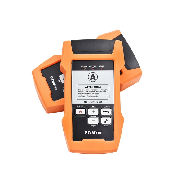
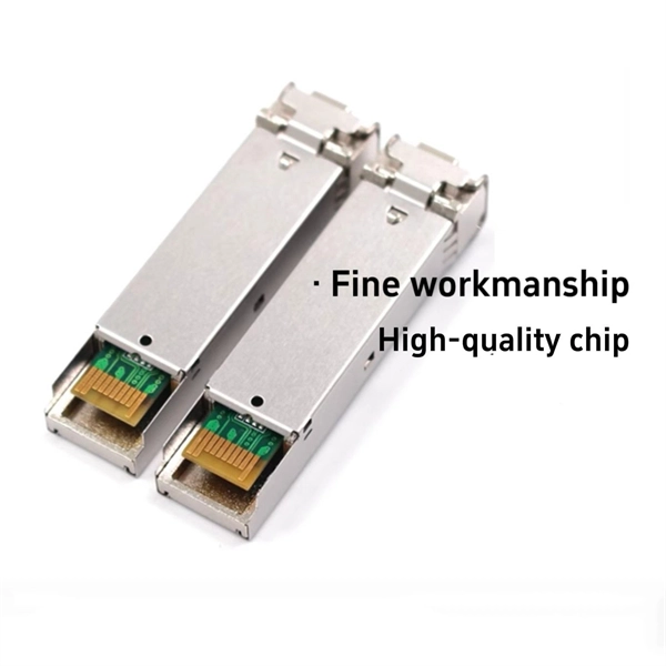
This comprehensive guide breaks down the internal structure, core components (TOSA, ROSA, lasers), and operational mechanisms of SFP optical modules, enriched with technical insights and real-world applications. SFP (Small Form-factor Pluggable) optical modules are compact, hot-pluggable transceivers that enable network equipment to connect seamlessly to fiber and copper links. As a leading provider of optical communication solutions, Weunion integrates these. One vital element in the data communication sector is the Small Form-factor Pluggable (SFP) module. In this blog, we will explore the inner workings of these modules, with a particular focus on three essential optical components: TOSA, ROSA, and BOSA. SFP modules are small, hot-swappable devices. Optical modules are devices used to connect network devices, transmit and receive data between network devices, and can be used to convert optical and electrical signals. The optical module is a very important component in an optical communication system. Think of it as the “translator” for your network equipment, converting electrical signals into optical signals. available with a variety of types of copper SFP and fiber SFPs, SFP+. This transceiver module is compliant wi h the small form-factor pluggable (SFP) multi-source agreement (MSA). They industrial performance with an extended operating temperature range. Through real-time monitoring, the DDM.
[PDF]
PLC Splitters are based on planar waveguide circuit technology. Inside the splitter, a silica glass substrate routes the incoming optical signal through a waveguide and evenly splits the light into the desired number of outputs. Planar Lightwave Circuit (PLC) Splitter is a type of passive optical component using silica optical waveguide technology to distribute optical signals from the Central Office (CO) to multiple premise locations, allowing for efficient communication. FS Bare Fiber Splitters are engineered for. It is widely used in passive optical networks to realize optical signal power splitting with 1xN or 2xN splitting ratio. Gigalight provides a series of customized PLC splitters to meet different Length, Output Fiber Type, Output Fiber Length, Input connector, and Output Connector etc. All. PLC optical splitters (planar waveguide optical splitter) is a key component in optical fiber communication networks and is widely used in optical fiber distribution systems such as FTTH (fiber to the home) and PON (passive optical network). They are fabricated with silica optical waveguide technology; maintain superior channel-to-channel uniformity and stability through a wide ange of environmental and mechanical conditions. All optical fibers used in Wirewerks PLC splitters are bend.
[PDF]

A ladder type cable tray tee is a fitting used to create a branch in a cable tray system, allowing cables to be routed in three directions. Its "T" shape provides a secure and efficient way to split cables from a main tray into two separate paths, ensuring organized and flexible. A cable tray tee and tee cover are components used in cable management systems to support and protect electrical and data cables. Here's a brief explanation of each:. Rigid steel cable tray tee fitting with zero tangent, safety bottom, and full accessory support. ventilation to heat producing cable such as power communication and other with the same or different width of the cable run. All fittings are available in sizes and types corresponding to the straight cable tray sections. These fitting are including: elbow, horizontal cross, vertical inside. NOTE : Equal or un equal tees can be supplied. When ordering state widths W1xW2xW3.. Office: 147/22 Nguyen Sy Sach Street, 15 Ward, Tân Binh Dist, HCMC,VN. Is it possible to connect 2 cabletrays with a "branch piece (left picture)" instead of a "tee (right picture)". The tee has 3 connectors, the branch piece only has 1 connector. I would like to ajust the "Type properties -> Fittings -> Tee" with the branch family, but can't get it accomplished.
[PDF]