The internal configuration of the single-phase distribution box consists of one phase (L), one neutral (N), one earth (PE) wire, and a single-phase busbar system. It also has the main switch and multiple MCBs for branch circuits, as well as for leakage protection with RCD or RCBO. A distribution box, or DB box, is a circuit breaker enclosure. It is a vital part and central hub of any electrical system. The hub distributes electrical power from a single input source to various circuits throughout a building. Whether it's a home, office, or factory, the DB box makes sure power. A distribution box is a key part of electrical systems in buildings. Inside, you'll find parts like circuit breakers and fuses that protect the system from problems like overloads and short circuits. It ensures that electricity flows. A distribution board (DB) is the central component of any power distribution system, providing a safe and organized way to deliver electricity from the main supply to individual circuits. What is a distribution board and why it matters is a fundamental question for engineers and designers of modern. This ultimate guide explains what a distribution box does, its internal components, common types, real-world applications, and how to select the right DB Box for your project. It provides convenience for protection, control and maintenance.
[PDF]

This handbook covers the code of practice in protection circuitry including standard lead and device numbers, mode of connections at terminal strips, colour codes in multicore cables, dos and donts in execution. Also principles of various protective relays and schemes including special protection. Read this document and the documents listed in the additional resources section about installation, configuration, and operation of this equipment before you install, configure, operate, or maintain this product. Users are required to familiarize themselves with installation and wiring instructions. presentation of protection and control relaying. The report will identify methodology behind these practices, present issues raised by the integration of microprocessor relays and the internal logic and external communication configurations, ying. The objective of this presentation is to convey a basic understanding of protective relays to an audience of engineers already familiar with low voltage protective device coordination. HT panel protection relay. The HT power supply is received from GO switch and distributed to the. The handbook for protection engineers includes guidelines on protective circuitry, protective relay principles, and testing procedures for switchgear and relays. It covers standard codes, wiring practices, and norms for protecting generators, transformers, and lines, and provides detailed.
[PDF]

The video tutorial demonstrates the depin and repin method for repairing automotive wiring harness connectors, specifically pigtails. It outlines seven easy steps to replace a pigtail connector, making it accessible for DIY enthusiasts and individuals dealing with electrical issues. This comprehensive guide will equip you with the knowledge and skills to accurately assess the integrity of a pigtail, helping you identify issues before they escalate into larger problems. We'll explore different testing methods, delve into the interpretation of multimeter readings, and offer. The latest in the line of Ford Flex Probe Kits, this newest release includes all the probes from the previous “D” kit, but now adds two each of the Micro Pin (. Additionally, all probes will now be printed with the tip size, helping technicians ensure usage of the properly sized tip. Short answer: An automotive wiring pigtail is a short section of wire with a pre-attached connector that lets you repair or replace a damaged plug without replacing the entire harness. It provides a plug-and-play repair solution that restores OEM fit, seal, and electrical reliability. Key steps. At FindPigtails. com, we specialize in high-quality, OEM connector replacement. Why pay thousands for a complete wire harness, when you can simply replace the damaged connector? We invite you to take a look at some of our instructional videos, for step-by-step guides of de-pin and re-pin procedures.
[PDF]
Read the topics and perform the procedures in this order: 1. Preparing for Installation 2. Planning a Switch Data Stack 3. Installing and Removing an SFP and SFP+ Module 6. Where To. The following information is for FCC compliance of Class A devices: This equipment has been tested and found to comply with the limits for a Class A digital device, pursuant to part 15 of the FCC rules. These limits are designed to provide reasonable protection against harmful interference when the. What Can I Do If a Message Is Displayed Indicating that an Optical Module Is Not Supported During Stack Port Configuration? - S300, S500, S2700, S5700, and S6700 V200R023C00 Configuration Guide - Device Management - Huawei How Do I Install a License File for a Stack System? How Do I Specify a. Page 1 Catalyst 3650 Switch Hardware Installation Guide April 2016 Cisco Systems, Inc. com Cisco has more than 200 offices worldwide. Addresses, phone numbers, and fax numbers are listed on the Cisco website at www. Text Part Number: OL-29734-01. Page 2 OR ITS. This guide describes the hardware features of the Catalyst 3650 switches. It describes the physical and performance characteristics of each switch, explains how to install a switch, and provides troubleshooting information. This guide does not describe system messages that you might receive or how.
[PDF]

Introducing the BS EN IEC 61439-3:2024, the latest standard for low-voltage switchgear and controlgear assemblies, specifically designed for distribution boards intended to be operated by ordinary persons (DBO). There are specific rules and standards for installation, handling and maintenance of machines and devices. Every German and European standard has to be approved by a series of institutions, including the "International Electrotechnical Commission (IEC)", the European comittee for electrotechnical. IEC Standards help in the measuring of that loss. With rapidly increasing global population and the industrialization of developing countries, comes soaring demand for energy – particularly electric power. According to the International Energy Agency (IEA), by 2040 global energy needs will have. IEC 61439-3 Ed. What Is the Purpose of a Distribution Board? An. The IEC (International Electrotechnical Commission) and BS 7671 (British Standard for Electrical Installations) both provide essential requirements for electrical installations, including those for fuse boards like garage unit, consumer unit and distribution board. While the IEC 60364 standard. We would like to hear your views on this material or activity. Please click here to provide your feedback. The publication cannot be displayed in the document viewer.
[PDF]
The proposed study will be based on three components, namely: (A) support to the establishment and operationalisation of the Digital Development Agency (DNA); (B) the elaboration of a Master Plan for the development of broadband infrastructures, a decision support tool for the. The proposed study will be based on three components, namely: (A) support to the establishment and operationalisation of the Digital Development Agency (DNA); (B) the elaboration of a Master Plan for the development of broadband infrastructures, a decision support tool for the. This intervention concerns the support to the setting up and operationalisation of the National Digital Agency (ADN), the elaboration of a Master Plan for the development of broadband infrastructures and the complete feasibility studies of the Central African Fiber Optic Corridor, DRC component. OTTs and telcos, such as Facebook or Orange, supported by funders and African governments, have joined forces to accelerate the deployment of high-speed connectivity infrastructures. The Congolese Minister of Telecoms, Augustin Maliba, signed the related memorandum of understanding (MoU) on April 7, 2025. "With the support of the. Learn about the market conditions, opportunities, regulations, and business conditions in congo, the democratic republic of the, prepared by at U. Embassies worldwide by Commerce Department, State Department and other U. agencies' professionals Democratic Republic of the Congo -.
[PDF]

This guide explains how to make 90° bends, vertical bends, tees, and offsets in wire mesh cable trays safely and professionally. Horizontal 90° Bend (Flat Bend) 2. Tee (T-Junction) Bend 4. Since the jaws of the bolt cutter drags a layer of zinc across the cut end and forms a protective layer. When a wire cable tray is cut, the fact that a. Wire mesh cable trays are widely used because of their flexibility and easy on-site modification. Unlike perforated trays, bends can be created directly at site without expensive fittings. Great if you are new or just forgot how to do it, this easy to follow guide makes it so simple. more The Easy Guide to. This involves a few essential steps to ensure a successful bending process. The first step in preparing the. The method for producing bridge bend elbows is as follows: Take a 90-degree cable tray bend elbow as an example, and apply the same principles for 45-degree bends accordingly. The length of the bottom side (bottom diagonal) after bending the cable tray should be equal to the width of the cable. OTHER THAN 90 ̊ JUNCTIONS Use this guide to learn the most effective installation practices when installing Cablofil tray. Each example of bends and tee's clearly illustrate proper tray cutting combined with recommended usage of Cablofil accessories. Engineers and contractors in North America and.
[PDF]
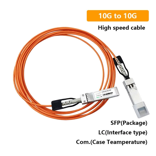
One key aspect of this progression is the advent and evolution of transceivers, specifically SFP, SFP+, SFP28, QSFP+, and QSFP28. Let's delve into each of these technologies to understand their specifications, differences, and applications. A Cisco compatible SFP list 2026 represents a validated inventory of optical transceivers that utilize Multi-Source Agreement (MSA) standards to provide identical functionality to Cisco Original Brand (OB) optics. Deploying these modules allows network architects to reclaim up to 80% of their. —— Explosive Growth of 800G/1. 6T Technologies, Scene-Based Selection + Finisar Original Solutions in One Stop In 2026, driven by AI computing power, optical modules have entered a critical era of rate iteration, technological restructuring, and scenario segmentation. 800G has become the mainstream. Choosing the right Small Form-factor Pluggable (SFP) transceiver is critical for network engineers and procurement specialists aiming to optimize performance, cost, and reliability. This SFP buying guide offers a detailed technical comparison, real-world deployment insights, and practical selection. ity with compelling economics. Our ONE Network platform simplifies management of Cambium Networks' wired and wireless broadband and network edge technologies. Our customers can f iness rather than the network. We mak. SFP+ 10G ZR is designed for stable 80km single-mode transmission where standard 10G optics fail.
[PDF]
5″ hard drive with a storage capacity of 80GB and featuring a IDE interface. ST380011A Seagate Barracuda 80GB 7200RPM ATA/EIDE 2MB Cache 3. 5-inch Low Profile (1. All information about the Seagate ST380011A hard disk drive: technical parameters, failure. 8-Mbyte buffer on: ST3200822A, ST3160023A, ST3120026A, and ST380013A High instantaneous (burst) data transfer rates (up to 100 Mbytes per second) using Ultra DMA mode 5. Giant magnetoresistive (GMR) recording heads and EPRML technology, which provide the drives with increased areal density. Manuals and User Guides for Seagate Barracuda 7200. 7 ST380011A Drive manuals available for free PDF download: Product Manual, Installation Manual Figure 3. Breather Filter Hole Location Figure 4. Ultra ATA. 1. 7 Plus • ST3160023A • ST3120026A • ST380013A Barracuda 7200. 7 • ST3160021A • ST3120022A • ST380011A • ST360014A • ST340014A These. HITACHI HDS721032DLE630 (320 GB S-ATA Gen3) SAMSUNG HS10XJC (100 GB IDE) SEAGATE ST9250612NS (250 GB S-ATA Gen3) Device manufacturers may change any parameters without prior notice. There is no warranty that the information listed here is complete and accurate. If you encounter any improper value. Our goal is to provide you with a quick access to the content of the user manual for Seagate Barracuda ST380011A. If looking through the.
[PDF]

To properly remove the optical cable: Locate the port > Stabilize the device > Gently grasp & pull the plug (not the cable) straight out > Do the same with the other end > Cover both connectors with plastic tips. To remove the plastic tip: Gently twist and pull off the protective plastic tip from. How To Unplug Optical Audio Cable | How To Remove Optical Cable. For inquiries: tutorialswithterry@gmail. more Sound or visuals were significantly edited or digitally generated. For. Understanding how to remove optical cable is crucial for maintaining the integrity of your audio setup and ensuring a seamless transition between devices. In this guide, we will navigate the intricacies of safely detaching optical cables from various connectors, exploring the proper techniques and. If you have an audio system setup using optical cables, you can easily remove the cables should the need arise for repairs, improvements or replacement. Turn around the first device from which you want to disconnect the optical cable. You should try to get as much access to the cable as possible. In this article, we have provided a step-by-step guide on how to remove a digital optical cable from a TV and also have included some additional tips that you must follow while removing the cable from your TV. So, what are you waiting for? Let's read and remove the cable. Why Does Correctly Remove.
[PDF]

Use the SWD or JTAG interface to connect the ST-Link v2 to the STM32 microcontroller. Download and install STM32CubeIDE or another compatible IDE. Install the ST-Link USB driver (available on the STMicroelectronics. The ST-LINK/V2 is an in-circuit debugger/programmer for the STM8 and STM32 microcontrollers. The single wire interface module (SWIM) and the JTAG/serial wire debugging (SWD) interfaces facilitate communication with any STM8 or STM32 microcontroller operating on an application board. ATOLLIC, IAR and KEIL Integrated Development Environments for. How do you use SWD (Serial Wire Debug) for debugging STM32? - HackMD Using SWD (Serial Wire Debug) for debugging STM32 microcontrollers is a powerful way to monitor and control code execution, inspect registers, and analyze faults. Here's a step-by-step guide to set up and use SWD effectively: 1. In addition. This small guide will explain how to connect your debugger to your development board. There are two commonly used connectors which expose only the SWD (Serial Wire Debug) interface or the full JTAG interface. If you are using one of ST's official Nucleo or Discovery boards, you do not have to. To upload a program to a chip from Thomson Semiconductor you need an ST-Link programmer device to connect your PC. Thompson sells branded programmers, adaptors and cables. We'll use an inexpensive ST-LinkV2. They look like AVR programmers but you need to read the pinouts on the side.
[PDF]

In this tutorial, we'll show you how to set up a modem router from the Chinese brand Unicom. If you've purchased this device and don't know where to start, don't worry. You can set it up and be ready to surf the web in a few simple steps. Follow these steps and you'll be able to enjoy a stable and. DHCP Server lets you manage assignment of Internet Protocol addresses on your router's Local Area Network. Change Password lets you change the router's Web User Interface login password. The Primary Setup function governs the connection between your router and your WAN, or Internet, service. The. How to change the wifi password of China Unicom router? 1. Enter the router background management address 192. The default. The NAT technology, which is typically implemented in a router, converts the private IP addresses (such as in the 10. 0 range) of the node on the internal private network to one IP address or one of several IP addresses for the public Internet. NAT not only conserves public IP addresses, but it. View & download of more than 188 UNICOM PDF user manuals, service manuals, operating guides. Switch, Media Converter user manuals, operating guides & specifications. Learn how to access your China Telecom router using the default IP address 192. 1 and admin credentials. This step‑by‑step guide explains how to make sure your computer is on the same network, find or reset the default username and password, and change your Wi‑Fi password.
[PDF]
Instantly reprogram, test, and unlock universal compatibility for every optical module — with full diagnostics and OTA updates built in. It lets you check the health of any SFP or QSFP module and program them effortlessly in seconds. We're cutting prices across the entire Ubiquiti SFP lineup — up. SFPTotal devices are full-compatible with official software SFPTotal Wizard which provides a convenient interface that allows to read, decode, edit and write changes to the memory of optical transceivers GBIC, SFP, SFP+, SFP28, XFP, QSFP+, QSFP28 and QSFP-DD form factors. Copy or write optical module profiles instantly. MFT (Mellanox/NVIDIA Firmware Tools) is a set of firmware management utilities for querying firmware details, performing firmware upgrades, and other configuration tasks. It includes four main components: mst, mlxburn, flint, and Debug Utilities. For full specifications, refer to the official. Reprogram and Diagnose Optical Modules Instantly with SFP Wizard The Ubiquiti UACC-SFP-Wizard is a portable, all-in-one optical module programmer and diagnostic tool designed for IT.
[PDF]
Selecting the right distribution board types depends on load capacity, circuit protection requirements, and compliance with IEC 61439 and SASO standards mandatory in Saudi Arabia. Engineers evaluate voltage rating (230V/400V), form of separation, and environmental IP rating. Saudi distributors and contractors increasingly demand distribution boxes with customizations. Common requirements include: Pro tip: Work with local contractors early - they'll help you navigate unique requirements that aren't obvious in SASO documentation, ensuring your products align with Saudi. REV. The objective of Power Distribution System is to deliver the Electrical power to customers in safe, reliable and most economical way such that the customer receives a supply of Electrical power required by him at the time and place at which he can use it. Several parameters of an Electricity supply. Explore the technical codes and standards applied in the electricity sector to ensure top-tier quality, safety, and protection in the delivery of electrical services. It covers the following topics: This publication does not relieve the designer of responsibility for accurately determining design arrangements and/or complying with. ' DISTRIBUTION PLANNING STANDARD ISSUE DATE Dec.,2022 Page 1 of 182 REVISION 01 DISTRIBUTION PLANNING STANDARD Saudi Electricity Company ' DISTRIBUTION PLANNING STANDARD ISSUE DATE Dec.
[PDF]

Fusion splicing is the process of fusing or welding two fibers together usually by an electric arc. Fusion splicing is the most widely used method of splicing as it provides for the lowest loss and least reflectance, as well as providing the strongest and most reliable joint between. This guide reveals the secrets to fusion splicing with little fluff—just proven, straightforward techniques refined from years of work in the field. The goal is to fuse the two fibers together in such a way that light passing through the fibers is not scattered or reflected back by the splice, and so that the splice and the region surrounding it are almost as strong as the. A fusion splicer is a specialized tool used in fiber optic networks to join two fiber optic cables together permanently. This process creates a strong and reliable connection that can withstand. Splicing fiber optic cable is an extremely important phase for making dependable, high-speed communication infrastructures. Fusion splicing stands out as a superior technique for joining optical fibers, offering a seamless, low-loss connection that is crucial for reliable fiber optic networks. Let's explore the fundamentals of mechanical and fusion.
[PDF]