This comprehensive guide will explore the importance and benefits of this integration, provide an understanding of fiber optic cable and Ethernet ports, discuss their compatibility, and offer a step-by-step process for connecting them. Proper connection of fiber optic cables is essential to harness these benefits fully, as even minor errors can lead to significant performance issues like signal loss. This article will guide you through the necessary tools, materials, and methods on how to connect fiber optic cables effectively. Using an optical cable involves connecting it to the right equipment, ensuring proper installation, and testing the system for optimal performance. Here's a step-by-step guide on how to use optical cable effectively: 1. Check Compatibility of Equipment Ensure that your equipment (e., network. One powerful solution to achieve these goals is by connecting fiber optic cables with Ethernet ports. This comprehensive guide combines industry standards with field-tested practices to ensure you achieve a rock-solid. These transceiver modules are hot-swappable input/output (I/O) devices that plug into 100BASE, 1000BASE and 10GBASE ports (for SFP+), which connect the module port with the fiber-optic or copper network. The SFP transceiver modules are hot-pluggable I/O devices that plug into module sockets. The number one cause of signal loss in optical fiber installations is dirt on.
[PDF]
A fiber optic backbone network is the central framework of a network that connects multiple sub-networks, systems, and devices using high-capacity fiber optic cables. It serves as the primary pathway fo.
[PDF]
A fiber-optic cable, also known as an optical-fiber cable, is an assembly similar to an but containing one or more that are used to carry light. The optical fiber elements are typically individually coated with plastic layers and contained in a protective tube suitable for the environment where the cable is used. Different types of cable are used for in different applications, for exa.
[PDF]
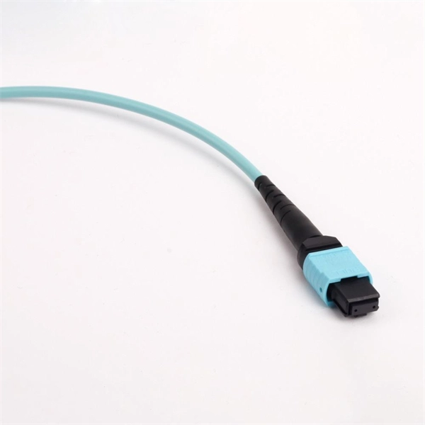
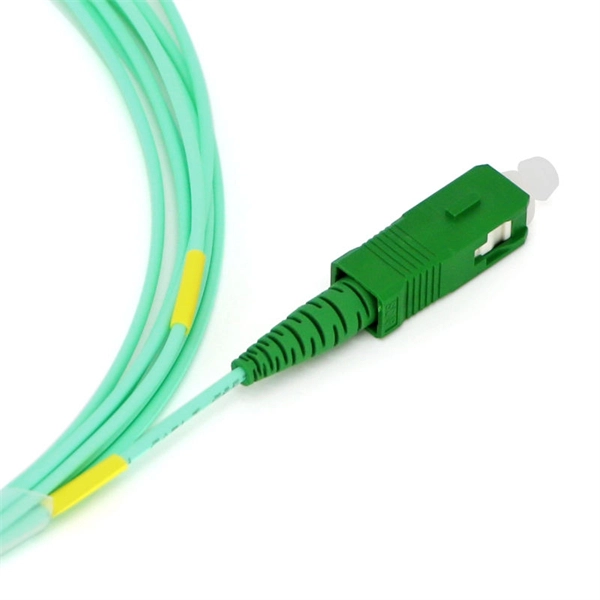
There are connectors designed for single mode and multimode fiber optic cables, which differ in core size, bandwidth, and optimal use cases as explained in this comprehensive guide to fiber optic cable.
[PDF]
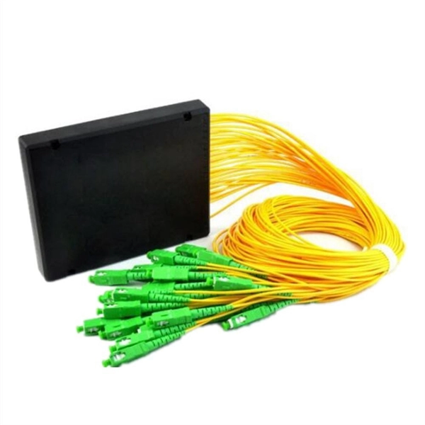
Calculate split loss, excess loss, and terminations for any ratio quickly today. See power budget impact instantly, then download a CSV or PDF summary. Use 2×N when two inputs feed the same distribution stage. Common values: 2, 4, 8, 16, 32, 64. Wavelength is recorded in. Fiber optic joints or terminations are made two ways: 1) splices which create a permanent joint between the two fibers or 2) connectors that mate two fibers to create a temporary joint and/or connect the fiber to a piece of network gear. Either joining method must have three primary characteristics. Optical fiber channel insertion loss is the decrease in optical power that occurs when an active transmitter is linked to an active receiver via terminated, optical fiber cables and patch cords and may include splice points and optical couplers. In general, loss is the natural decay of a signal. Telcordia and TIA allow a 0. 3 dB maximum splice loss. Connector loss is always measured as a mated pair. ITU & IEC allow 0. Splitter loss values are "Typical" and include a connector in and out. These terminations must be of the right style, installed in a. In this lesson, a long and very important one, you will learn about fiber splicing and termination. Wavelength is recorded in outputs for documentation.
[PDF]
Match trench method with the correct underground fiber structure (GYTS, GYTA53, GYTY53, micro-duct). Control pulling tension and bend radius – most damage happens during installation, not operation. Plan depth, backfill and warning markers early to reduce maintenance risk and. ion) and “ Installed” (after installation). The following formulas may be used to determine general guidelines for installing Corning Optical Communications fiber optic cable; however, refer to the cable specifi simply double the minimum working bend radius. Split cable guides and split 40-in. 1. 01 This best practices procedure provides general information for the installation of fiber optic cables in direct buried applications. The methods described are intended for guideline use only, as it is impossible to cover all the various conditions that may arise during an installation. Individual. Fiber optic cable transmits data as pulses of light through thin strands of glass, offering superior bandwidth and distance capabilities compared to traditional copper wiring. Direct burial is a common and highly effective method for external installations. ■ 1). Conventional trenching is suitable for open areas, while narrow trenching or horizontal directional drilling (HDD) is often preferred in urban or high-traffic environments to minimize disruption during underground fiber optic cable installation. Using Conduits to Protect Underground Fiber Cables In.
[PDF]

Top 5 Best Fiber Optic Cable Manufacturers in Pakistan As we venture into 2024, the landscape of fiber optic cable production in Pakistan has become both competitive and dynamic, featuring a blend of established giants and emerging challengers. Identify and compare relevant B2B manufacturers, suppliers and retailers Max. Pakistan Telephone Cables Limited (PTCL Cables) Pakistan Telephone Cables Limited (PTCL Cables) specializes in the manufacturing of various types of Optical Fiber Cables, showcasing a state-of-the-art production facility. This blog post highlights the top 10 best cable manufacturers in Pakistan, known for their quality, innovation, and customer satisfaction. Long Age Cables Long Age Cables is an ISO 9001:2015, PSQCA, and PEC certified cable manufacturer company in Pakistan and meets international and national. Pakistan Cables, founded in 1953 by Mr. Chinoy, is one of the oldest electrical wire manufacturers in Pakistan. The company has a rich history, including collaborations with BICC (British Insulated Callender's Cables) and later with General Cable, a Fortune 500 company. Pakistan Cables is. Pakistan Telecom Cables is a prominent manufacturer in the telecommunications industry, specializing in the production of various types of cables and related products. These electric cables.
[PDF]
The color sequence for 24-fiber optic cables is: composed of 4 tubes, each containing 6 fibers with the colors blue, orange, green, brown, gray, and white. The TIA/EIA-598-C standard is the most widely followed guideline for color coding in optical fiber cables, both for loose-tube and. The color sequence of optical fibers in loose tubes (Chinese National Standard fiber order) Common fiber optic cables include 4-fiber, 12-fiber, 48-fiber, 96-fiber, and 144-fiber cables. The color sequence for 12-fiber. The chromatographic arrangement of the loose tube within a general fiber optic cable and the chromatographic arrangement of the fiber within the loose tube is shown below: 1. Cores in Tube. Available in OS2/OM3/OM4 at factory-direct wholesale pricing. How to Identify Fibers in High-Count Cables (>12 Fibers) For cables with more than 12 strands (e., 48, 96, or 144 fibers), the industry uses a “Tube and Fiber” system. It is the cornerstone of virtually all high-bandwidth, long-distance communication networks today. A standard communication-grade optical fiber is a double.
[PDF]

Optical cable lines lightning protection and strong current protection are achieved by avoiding, guiding or discharging them underground to prevent lightning and strong current from causing damage to the optical cable lines themselves, communication equipment and personnel. Since the lightning. Fiber optic cables have good protection performance, and the metal components of cable's insulation value is so high that lightning current can not enter the cable easily. However, because fiber optic cable has strengthened core, especially the direct-buried fiber optic cable has armoring layer. rocess approved by the American National Standards Institute. This process brings together volunteers representing varied viewpoints and i terests to achieve consensus on fire and other safety issues. While the NFPA administers the process and establishes rules to promote fairness in the. The Lightning Protection Institute is a nationwide not-for-profit organization founded in 1955 to promote lightning protection education, awareness, and safety. The lightning protection industry began in the United States when Benjamin Franklin postulated that lightning was electricity, and a metal. Defines lightning parameters (current waveform, peak values, charge transfer), threat classification, and damage/loss categories. Provides the risk assessment methodology.
[PDF]
Hengtong Group was established in 1991 and is the largest optical cable manufacturer in China. They are committed to the development of comprehensive cabling systems and have established a complete optical communication product chain, from optical fiber to fiber optic cables to. This guide ranks China's top 10 fiber optic cable manufacturers for 2025, based on market share, production capacity, innovation, and global reach. The list prioritizes companies with strong export performance (to 100+ countries) and compliance with international standards like ITU-T G. 652 and IEC. This article will introduce the leading enterprises in China's optical fiber cable industry, revealing how they have secured a place on the global optical communications stage through profound technical expertise, continuous innovation, and forward-looking strategic planning. We will analyze the. This blog introduces the top 10 trusted fiber optic cable manufacturers in China, providing valuable insights for your business decisions. YOFC YOFC is a global leader in optical preforms, fibers cables, and integrated solutions. You can obtain their contact information in this post to contact them directly.
[PDF]
Filter your results below. The Marvell® PAM4 optical DSP portfolio, including Spica™ and Nova™ DSPs, addresses the critical the need for high-bandwidth optical interconnects to power AI infrastructure. Marvell leads the pluggable module ecosystem with low-power, high-performance silicon for AI, cloud, enterprise and 5G. MaxLinear's highly integrated PAM4 DSPs offer superior link-margin performance and low power to enable 100G, 400G, 800G, and 1. 6T optical interconnects inside the data center. DCP-M is a genuine open line DWDM platform, specifically engineered for contemporary DCI. While it possesses the form factor and user-friendliness of a passive multiplexer, DCP-M stands out by actively monitoring traffic, amplifying signals for extended distances, and accommodating higher data rate. In this context, the 100G DWDM PAM4 optical module, which combines the advantages of PAM4 modulation and DWDM technology, becomes an ideal solution. This article will explore the definition, features, advantages, application scenarios, and FS product highlights of 100G PAM4 DWDM optical modules. Watertown, CT – The Siemon Company, a global leader in high‑performance network infrastructure solutions for data centers and smart buildings, is proud to announce the launch of its portfolio of 200G, 400G, and 800G PAM4 high‑speed optical transceivers, expanding Siemon's end‑to‑end data center. DCP-M is a true open line DWDM platform designed specifically for modern DCI.
[PDF]
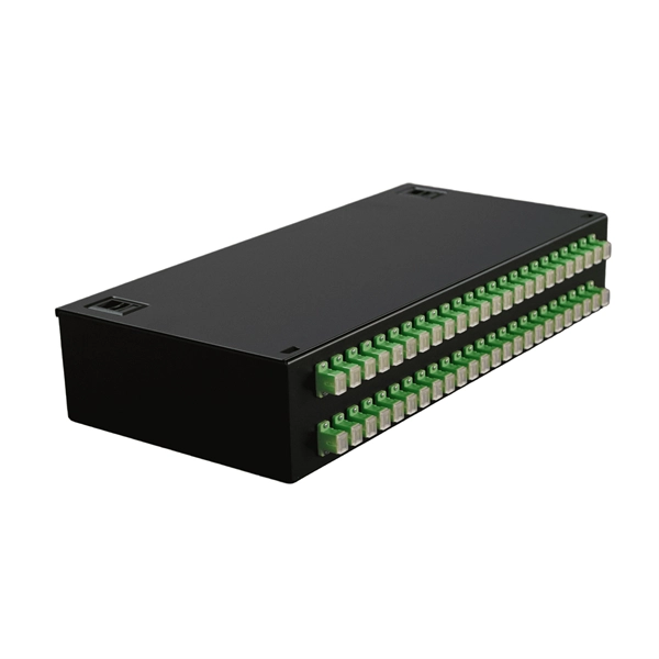
Get in touch with us at info@naurufibrecable. com for more information. Find here Fiber Optic Distribution Frame, Fiber Distribution Frame manufacturers & OEM manufacturers in India. This fiber optic distribution frame is a. We carry a comprehensive product range with focus on premier performance characteristics enhanced for the South Asian region We are a complete telecom solution provider, specializing in high performance data networking and interconnectivity solutions. Our primary objective is to provide state of. for 6 ports, 12 ports, 24 ports, 36 ports, 48 ports, 72 ports, 96 ports, 144 ports and more. For a long time, Huihongfiber has always been committed to providing customers with high-quality products and professional services. As an important partner with decades of experience in the optical fiber. Fiber distribution box is suitable for the wiring connection of optical cable and optical communication equipment, through the adapter in the wiring box, the optical jumper leads the optical signal, and realizes the optical wiring function. OTRANS strives to provide you with professional, reliable. Disclaimer : This category is intended for businesses looking for manufacturers, wholesalers, and bulk suppliers. The optical distribution frame (ODF) is a critical component in modern telecommunication networks, serving as a pivotal junction point for managing fiber optic cables.
[PDF]
Find Angola Cable manufacturers & suppliers with shipment details on Trademo. Access global exporters database and gain exporter insights. Angola Cables is an Angolan telecommunications multinational operating in the wholesale market. It sells international transmission capacity through submarine fiber optic cables and IP Transit and manages IXP Angonix in Luanda, Angola and the AngoNAP data center in Fortaleza, Brazil (Tier 3). Subscribe to global trade data intelligence to discover new business. As per Volza's Angola Import data, Optical fibre cable import shipments in Angola stood at 546, imported by 14 Angola Importers from 13 Suppliers. Angola imports most of its Optical fibre cable from Portugal, Netherlands and Brazil. The top 3 importers of Optical fibre cable are Brazil with 30,410. Contact us to understand how D&B calculated your company's specific ESG Ranking, provide new or updated information to ensure your company's ESG Ranking remains accurate and up to date, or dispute your current ranking. Unlock full sales materials and reports Dynamic search and list-building. Angola Cables is the leading South Atlantic submarine fiber optic cable system developer owner and wholesale operator. Over the period under review, the total consumption indicated a measured expansion from 2012 to 2025: its value increased at an average annual rate of X% over the last twelve years.
[PDF]

Per‑unit estimates often appear as $0. 50 per ft for basic fiber plus additional charges for trenching and install labor. Several drivers shape fiber installation pricing. Homeowners and businesses typically pay for fiber optic cable installation based on distance, conduit needs, and labor. The main cost drivers include material type, run length, trenching or aerial work, and any required permits or inspections. This guide provides clear cost estimates, price ranges. The initial cost of installing fiber optic cables can vary depending on the chosen installation method and specific project requirements. Total Project Costs: For commercial installations, expect costs ranging from $5,000 to $20,000 per mile for underground projects and from $40,000 to $60,000 per. Buyers typically pay for fiber laying by combining material costs, labor time, and permitting plus trenching or aerial support fees. A short residential drop under 1,000 ft may cost $3,000-$8,000, while longer runs to an attached garage or street node can run $8,000-$25,000. The price often reflects project scope, geography, and local regulations, making. Fiber optic cable costs vary widely – from $0. Installation can be more expensive than the cable itself, especially with site challenges.
[PDF]

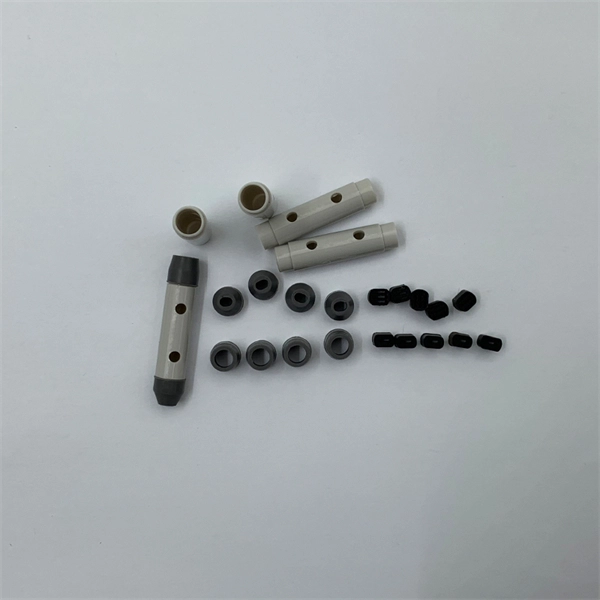
Fiber Optic Welding How To Joint Fiber Optic Cablesplicing fiber optic cable,fiber optic splice,fiber optic,fiber optics,fiber splice,how to splice,fibre opt. The optical fiber connection adopts the fusion splicing method. The whole process is similar to the welding of metal wires, and it is generally carried out by electric isolation. At the moment, there are two methods of connection: Thermal welding of optical fibers consists in bringing the ends of the conductor to melting using a fiber optic splicer, and more specifically - located inside the electrodes. The welded ends are then pressed and a weld is formed. The most work is waiting for installers, whose tasks can be divided into several stages: In this part, we will deal with the second stage, i. welding, which is considered to be one of the most difficult parts of installers' work in. Open the stripping tube and wipe the grease on the optical fiber with toilet paper and alcohol cotton. On the welding disc, make the optical fiber precoil first and cut the optical fiber into an appropriate length to facilitate the coil fiber work after welding. Add heat shrink tube. Procedure. Another method is to use the so-called mechanical welding. It uses special parts that are prepared in advance to connect the two ends. Thanks to this, you can connect two ends of the cable with a ready-made splice, without the need to use an optical fiber splicer. While this method may appear to be.
[PDF]