The process involves a combination of national infrastructure, local engineering, and property-level setup. In this guide, we'll break down the fiber installation process from start to finish and explain key components such as fiber cabinets, flower pods, ducting, and ONT setup. That's the kind of experience fiber-optic internet makes possible. Fiber optic internet is. Professional fiber optic installation companies ensure your network infrastructure meets current demands while supporting future growth through expert design, installation, and testing services. 85% of fiber network failures trace back to contaminated connectors—professional installation with. In the spirit of self-reliance and technical mastery, we've crafted this detailed guide to empower you to take control of your own network by installing fiber optic cables yourself. Our company specializes in high speed Ethernet, fiber optic, and any other medium of low voltage wiring. Our voice, data, audio, and video cabling installations and products are all top quality! We are an established. Your trusted source for structured voice & data cabling. We provide expert installation and maintenance for all your business communication needs in San Jose and surrounding areas. We offer San Jose and surrounding areas a one source solution for all your data cabling & business phone system needs.
[PDF]
These installation instructions provide overview and specification information for small form-factor pluggable (SFP/ SFP+/SFP28) modules, as well as instructions for installing and removing the modules. Small form factor transceiver modules (including SFP, SFP+, and SFP28 modules) plug into the SFP. Some Extreme Networks switches support the use of 25 Gb SFP28 pluggable optical modules. Each module provides one 25-gigabit transmit and receive channel. Use of 25Gb SFP28 modules in QSFP28 ports requires the use of the QSFP28 to SFP28 adapter (part no. Use only Extreme Networks-certified. The ESR SFP28 module provides a 25 Gb optical connection using an LC duplex optical connector over one pair of OM3 or OM4 multimode fibers. One data lane operates in each direction, at 25 Gbps up to 200 meters using OM3 fiber or up to 300 meters using OM4 fiber. The fiber-optic SFP modules contain a laser that is classified as a “Class 1 Laser Product” in accordance. LINK-PP offers a full range of optical transceivers and SFP module for modern data centers, telecom networks, and enterprise infrastructures. Our portfolio spans data rates from 1G to 400G, including SFP, SFP+, SFP28, QSFP+, QSFP28, QSFP-DD, and OSFP modules, designed for both single-mode and.
[PDF]
Match trench method with the correct underground fiber structure (GYTS, GYTA53, GYTY53, micro-duct). Control pulling tension and bend radius – most damage happens during installation, not operation. Plan depth, backfill and warning markers early to reduce maintenance risk and. ion) and “ Installed” (after installation). The following formulas may be used to determine general guidelines for installing Corning Optical Communications fiber optic cable; however, refer to the cable specifi simply double the minimum working bend radius. Split cable guides and split 40-in. 1. 01 This best practices procedure provides general information for the installation of fiber optic cables in direct buried applications. The methods described are intended for guideline use only, as it is impossible to cover all the various conditions that may arise during an installation. Individual. Fiber optic cable transmits data as pulses of light through thin strands of glass, offering superior bandwidth and distance capabilities compared to traditional copper wiring. Direct burial is a common and highly effective method for external installations. ■ 1). Conventional trenching is suitable for open areas, while narrow trenching or horizontal directional drilling (HDD) is often preferred in urban or high-traffic environments to minimize disruption during underground fiber optic cable installation. Using Conduits to Protect Underground Fiber Cables In.
[PDF]
Find accurate cable prices in Uganda based on brand, quality, and manufacturer. Compare top suppliers, check MOQs, and get the best deals. Click to explore verified options today!. A 100-meter (328 ft) HDMI fiber optic cable is an active hybrid cable (fiber + copper) designed for. 1M LC_LC DUAL FIBER PATCH CORD: High-performance duplex multimode fiber optic cable with LC. Type: High-speed HDMI 2. Resolution Support: Capable of supporting 4K Ultra HD. Optical Audio Cable, 1. BOX 75720, PLOT NO 6 OPP. VICTORIA UNI (ESSO CORNER), JINJA ROAD, KAMPALA, UGANDA Copyright © Tronic Uganda Limited All Rights Reserved. The Ugandan cable market is rapidly evolving, driven by digitalization and infrastructure development. Prices are tightly linked to brand reputation and manufacturer sourcing, creating distinct tiers. Buyers must navigate between premium international brands, reliable mid-tier options, and. Cable Corporation Ltd was founded in 1968 and is today Uganda's oldest and largest cable and conductor manufacturing company. LV and Domestic Cables, and Transmission Conductors. Cable Corporation Ltd has two divisions. Cable Division and Engineering Division. Entire range of domestic cables – from. Volza's Global Partner Finder scans 3. 5 billion+ shipment records with 20+ precision filters to uncover the most reliable and economical suppliers for you. Volza's data confirms a robust and dependable Optical Fibre Cables supply network.
[PDF]
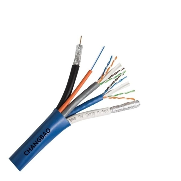
Fiber optic cables often follow a color-coding system to indicate their type: Single-mode fibers - Typically yellow. Multi-mode fibers (OM1 & OM2) - Usually orange or sometimes gray. Choosing the right type of fiber optic cable is essential for reliable and cost-effective network performance. The two main types — Single Mode (SM) and Multimode (MM) — differ in construction, performance, and application. This guide explains how to identify them by appearance, labeling, and. When figuring out if a fiber cable is single mode, one must know the different classifications. Essentially, fiber optics are mainly categorized as: Single Mode Fiber (SMF): This type features a small core and uses laser technology to send a single light mode. Single mode fibers are used for. Knowing how to tell the difference between single mode and multimode fiber is crucial for network efficiency; the core distinction lies in the fiber's core diameter and how light travels through it, affecting bandwidth, distance, and cost. This allows for a single mode of light to travel through the core. With clear tables and updated details, it serves as a comprehensive reference for technicians handling modern fiber optic installations. We'll cover single mode, multimode, and armored fiber cables below. This small diameter core, typically around 9 microns in diameter, allows only one.
[PDF]

To use a power meter for fiber optic testing, always clean connectors first with lint-free wipes or click-to-clean tools. Select the correct wavelength and set your reference. You measure optical power in dBm or insertion loss in dB. Consistent procedures ensure accuracy. Verify light travels from. The most basic fiber optic measurement is optical power from the end of a fiber. This measurement is the basis for loss measurements as well as the power from a source or presented at a receiver. Typically both transmitters and receivers have receptacles for fiber optic connectors, so measuring the. An optical power meter measures the strength of light traveling through a fiber optic cable, giving you a reading in dBm (decibels relative to one milliwatt). This article will guide you through the methods, instruments, and key considerations for measuring fiber. Fiber optic cabling is the high-performance core of today's datacom networks. As network speeds and bandwidth demands increase, fiber performance requirements have become more stringent. Fiber testing is more important than ever. An OPM uses a photodiode to generate an electrical current proportional to optical power.
[PDF]
In 1880, and his assistant created a very early precursor to fiber-optic communications, the, at Bell's newly established in. Bell considered it his most important invention. The device allowed for the of sound on a beam of light. On June 3, 1880, Bell conducted the world's first wireless transmission between two buildings, some 213 meters apart. Due to its use of an atmospher.
[PDF]
Fiber testing is the process of verifying the performance of optical fiber cabling. This process includes a range of tests and measurements such as insertion loss, optical return loss, and fiber length. It encompass.
[PDF]

A novel method for aligning multi-core fibers (MCF) provides a systematic approach for MCF splicing in the lab, in cable factories, and in the field. Splicing fiber optic cable is an extremely important phase for making dependable, high-speed communication infrastructures. Regardless of the type of fiber network you're deploying, be it for telecom, enterprise data centers, or smart city infrastructure, fusion splicing provides the benefits of. This is where fiber optic cable splicing—the process of creating a permanent, high-performance join between two fiber ends—becomes critical. For network managers and technicians, a poor splice can lead to significant signal degradation, network downtime, and costly troubleshooting. At Turn-Key. W. Zheng, "Automated Alignment and Splicing for Multicore Fibers," in Optical Fiber Communication Conference/National Fiber Optic Engineers Conference 2013, OSA Technical Digest (online) (Optica Publishing Group, 2013), paper OM3I. However, realising its potential depends on one critical process, which is achieving ultra-low-loss fusion splices that maintain performance and. This guide reveals the secrets to fusion splicing with little fluff—just proven, straightforward techniques refined from years of work in the field. The guide provides the complete workflow, covering safety precautions, tool selection, fiber preparation, fusion operation, quality control, and.
[PDF]
Shop ADSS fiber optic cables designed for aerial installations. All-dielectric, self-supporting fiber ensures durable, high-performance outdoor connectivity. American Tech Supply is your reliable source for ADSS (All-Dielectric Self-Supporting Cable), Fiber Cable, Ribbon Cable, Armored, Gel and Gel Free Single-Mode Fiber cables. We offer a wide range of options, from 6 fibers to 144 fibers, all the way up to 432 fibers and even 6904 fibers, which are. All Dielectric Self Supporting cable or more commonly referred to as ADSS cable is a type of fiber optic cable that is used in aerial applications. This type of cable does not need a messenger to support it, so it can be installed in a single pass. This cable construction does not contain any. ADSS Fiber Cable, 96 ct., Singlemode, Single Jacket, Loose Tube, SMF28e, Dry/Dry, 500′ Max Span NESC Medium Load, Price Per Ft. Fiber Optic Cable 258 Original Std ADSS Flex-Span ADSS New Std ADSS Applications • Electric utility transmission lines – Typically framed under conductors • EHV environments – Tracking-resistant options available Features • Up to 432 fibers in cable – Gel-Free Buffer Tube options available – up to. OMC ADSS (All-Dielectric Self-Supporting) fiber optic cable is a specially designed cable for aerial applications.
[PDF]
This article outlines five specific steps for repair: 1) Identify the break; 2) Cut out the damaged section; 3) Strip the cable; 4) Trim the fiber ends; 5) Test the repair. DIY fiber optic cable repair kits are increasingly popular for those who prefer home repairs. Before diving into repairs, it's essential to grasp the basics of fiber optic cables. These cables consist of a core (glass or plastic) that carries light signals, surrounded by cladding to reflect light inward, a buffer for protection, and an outer jacket for durability. Single-mode fibers (SMF). With the right tools and techniques, you can efficiently repair damaged fiber cables and restore reliable performance. The first step requires that you find the damage. To do this, you can use an OTDR, Optical Time Domain, Reflectometer. This is a testing device that looks at optical signals in the cable which can identify irregularities in the structure. This involves a set of specialized equipment such as a fusion splicer, fiber cleaver, and fiber stripper, among others. When it comes to ensuring nice network experiences for users, the condition of a fiber. A cut or damaged fiber optic cable can disrupt your network, but it is repairable with the right tools and techniques.
[PDF]

Optical cable lines lightning protection and strong current protection are achieved by avoiding, guiding or discharging them underground to prevent lightning and strong current from causing damage to the optical cable lines themselves, communication equipment and personnel. Since the lightning. ntly, there are a limited number of industry documents that address the requirements for optical fiber cables near high voltage circuits. One standard that has been developed by the Institute of Electrical and Electronics Enginee s, Inc (IEEE) is 1222, “IEEE Standard for All-Dielectric. The Fiber Optic Association, Inc. (FOA) was founded in 1995 to help develop the workforce to build the fiber optic networks to support a rapid expansion in communications and the Internet. ” It defines the requirements for ADSS cables placed aerially in a high. This Recommendation provides a procedure to protect the telecommunication lines using fibre optics against direct lightning discharges to the line itself or to the structures that the line enters. The protection procedure is related to the exposure of the line to direct lightning discharges and. Armored Cable: For direct burial or areas prone to crushing, use armored fiber optic cables that have an additional layer of metallic or non-metallic protective sheathing. Cable Trays and Ladders: In data centers and industrial settings, use cable trays or ladders to support runs, keeping them off.
[PDF]

What is the main cause of attenuation in fiber? Attenuation in fiber mostly happens from absorption and scattering. The fiber material takes in some light as it moves. Both of these things make the signal weaker as it goes through the. Optical Signal Attenuation is the single greatest factor limiting the distance and performance of your network. Understanding it is crucial for anyone involved in data centers, telecommunications, or enterprise networking. This guide will demystify signal loss, explore its causes, and show you how. Optical fibers are a key component in modern communication systems, carrying signals over long distances. However, even the most advanced optical fiber suffers from attenuation, which is the loss of signal power as it travels along the fiber. Understanding the causes of signal loss and implementing mitigation strategies is essential for maintaining network efficiency. From infrastructure planners to telecom engineers. Optical fiber technology enables rapid data transmission over vast distances by guiding light signals through thin strands of glass. Losses can be introduced by various means such as intrinsic material absorption, scattering, bending, connector loss and more.
[PDF]
Optical fiber consists of a and a layer, selected for due to the difference in the between the two. In practical fibers, the cladding is usually coated with a layer of or. This coating protects the fiber from damage but does not contribute to its properties. Individual coated fibers (or fibers formed into ribbons or bundles) then ha.
[PDF]

Fiber optic loss calculation formula: Total link loss (LL) = Cable attenuation + Connector attenuation + Fusion attenuation [Note: If there are other components (such as attenuators), their attenuation values can be added]. Intrinsic Optical Fiber Losses comprise of absorption loss, dispersion loss and scattering loss caused by the structural defects. The detailed information about these optical losses and how to reduce them are. Calculate fiber optic signal loss based on cable length, attenuation, and connector losses. Determine cable loss, connector loss, and total system loss in decibels (dB) to assess signal quality and repeater requirements. Fiber optic loss is calculated in two parts: cable loss and connector loss. This calculator determines fiber loss based on input power, output power, and the length of the fiber optic cable. In summary, fiber optic loss is. Use this worksheet to input values for all variables that will impact your system's performance. After entering your values, please ensure you click the 'Calculate Link Loss' button at the bottom of the page to generate your total link loss. This step is necessary to see if your system falls within. Optical fiber loss is a term for signal loss affecting transmission reliability. Optical fiber loss is.
[PDF]