We supply 1X9 Single Mode Fiber Optical Transceiver and 1X9 Multi mode Fiber Optical Transceiver, RoHS compliant fiber optic transceiver modules. 1x9 optical transceiver modules are state-of-the-art components designed expressly for the building of high-speed bi-directional communication links that require data rates of up to 1. The modules operate at special extended voltage and temperature (-10 to 85 C) ranges. 1x9 optical. North America Fiber Optics (NAFO) is the sole distributor of Coretek Opto, a leading fiber optic transceiver and optical component manufacturer based in Taiwan. Coretek offers a comprehensive portfolio of high-quality optical products ranging from legacy optical modules to next-generation. 1x9 transceivers are the earliest and oldest-style optical modules. Initially created in the 1990s, they aimed at 100M/1G Ethernet, Fibre Channel, ATM, FDDI, SDH/SONET, and video applications. Then, they were gradually replaced by more advanced and intelligent GBICs, SFPs, SFP+, and QSFPs. 9-pin DIP transceivers for very-legacy switches built before the SFF/SFP standards. Replaces discontinued Methode / Stratos / Optech parts. The original optical module form factor (mid-1990s). It is usually directly cured on the circuit board of the communication equipment and used as a fixed optical module. The 1X9 optical transceiver module can be divided. You are here: Home >> Product >> Optical Transce. >> 1X9 Transceiver.
[PDF]
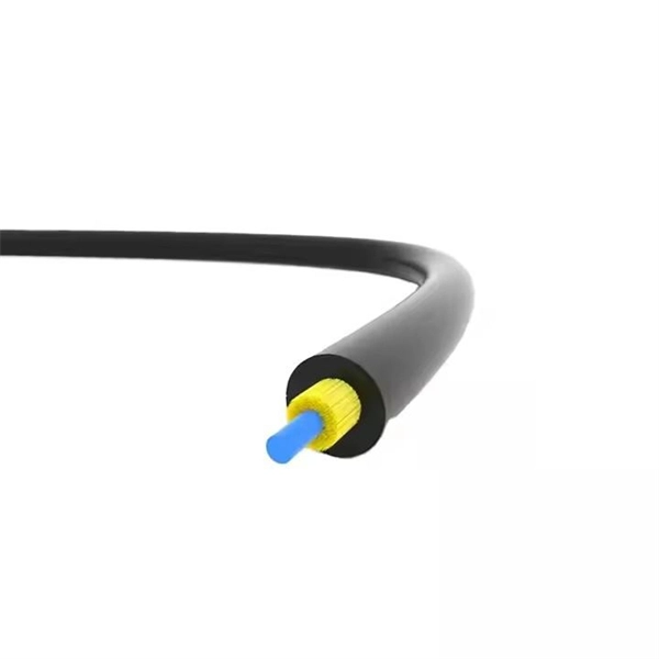
It is designed to transmit data in one direction only. The single-mode optical fiber is designed and engineered to carry one single light mode in a minimal core diameter. It is specified as the best for especially long-distance applications than multimode fiber. Higher-order modes like LP 11, LP 20 etc. Modes are the possible solutions of the Helmholtz equation for waves, which is obtained by combining. Simplex fibers are most commonly used in applications that only require data transmission in one direction. Digital data readouts, interstate sensor relays, and automatic speed and boundary sensors (for sports applications) are all important uses for simplex fiber optic cables. It is designed to. Simplex single-mode fiber is typically used in scenarios where data only needs to be sent in one direction, such as in sensor application like a fire alarm system that sends signals from detectors to a control panel might use simplex fiber. Duplex single-mode fiber is commonly used everywhere else. Single fiber modules (BiDi) use one fiber for both transmitting and receiving data. This saves space and money. Dual fiber modules use two fibers.
[PDF]

Click to get your 800G transceiver modules and cables from nearby warehouses. 30-Day Free Return. Trusted by 260K+ Enterprise Users. Cisco QSFP-DD and OSFP 800G ZR/ZR+ digital coherent optics modules enable 800G traffic over amplified Dense Wavelength-Division Multiplexing (DWDM) links up to 120 km for 800ZR and over 1000 km for 800G ZR+. Our sales manager will contact you soon. High-density 800G OSFP and QSFP-DD transceivers support InfiniBand and RoCE, enabling 100m to 2km transmission via MMF and SMF. Know how QSFPTEK make sure your order gets to you on time. Review your item's return/exchange eligibility or warranty period. Select reliable payment options for quick and easy transactions. View the daily routine of QSFPTEK's high-spec production chain. QSFPTEK is a leading high-tech company which. The Forara 400G OSFP, 400G QSFP-DD and 200G QSFP-DD products are hot-pluggable, high-density and low-power, designed for use in 400 Gigabit Ethernet and 200 Gigabit Ethernet links over data center, high-performance computing networks, enterprise core and distribution layers, and service provider. Connlight's product specification covers the performance of the OSFP to QSFP-DD Adaptor Module that offers 800 Gigabit Ethernet transfer to 400、200、100 or 40 Gigabit Ethernet connectivity for OSFP only. it allows smooth and cost-effective migration to 800 Gigabit Ethernet by providing an option to.
[PDF]
Single fiber modules (BiDi) use one fiber for both transmitting and receiving data. This saves space and money. They are easier to set up and give steady communication. They use a thin fiber. What is Single Mode Fiber Optic Cable, and How Does it Work? A single-mode fiber optic cable is an optical fiber designed to propagate light signals over long distances with minimal attenuation. It comprises one glass or plastic fiber and features a tiny core of about 8-10 microns in diameter. This. o In optical modules, "core" refers to the light-transmitting channel in the fiber. o Think of a highway. A 1-core fiber is like a single-lane road—only one car (or data signal) can travel at a. If you're upgrading your network and deciding between single-mode SFP and multimode SFP modules, this can be more than just an equipment decision; it can impact your reach, performance, and budget! Knowing the basic differences, as well as the real-world scenarios, will help you ensure you're. SFP (Small Form-factor Pluggable) is a compact, hot-pluggable network interface module used to connect network devices (switches, routers, firewalls) to fiber optic or copper cables. Modes are the possible solutions of the Helmholtz equation for waves, which is obtained by combining.
[PDF]
The CFP, short for C form-factor pluggable, is a multi-source agreement to define the form-factor of the optical transceiver for high-speed digital signal transmission. CFP transceivers are defined by CFP MSA to enable 40 Gb/s, 100 Gb/s and 400 Gb/s applications. The c stands for the Latin letter C used to express the number 100 (centum), since. What is a CFP optical module? Is it still relevant in 2026? And when should you choose it over newer alternatives? This guide is designed to answer those questions with clarity and technical depth. In this comprehensive article, we will delve into the world of CFP optical transceiver modules, exploring their. What is CFP Modules? Complete Guide to Standards, Variants, Comparisons, and Applications What is CFP Modules? Complete Guide to Standards, Variants, Comparisons, and Applications What is CFP Modules? Complete Guide to Standards, Variants, Comparisons, and Applications In the era of cloud. This article breaks down the key differences between CFP, CFP2, CFP4, and CFP8 optical transceivers commonly used in fiber optic networks. Figure 1: Dimensions of CFP, CFP2, CFP4, and CFP8 The table below summarizes the specifications of each form factor: 24 W (Max. ) In essence, the progression.
[PDF]
This installation note provides the installation instructions for the Cisco small form-factor pluggable (SFP) and SFP+ transceiver modules. This document is intended to serve as a guide for architecting and deploying fiber optic networks in a customer environment. These transceiver modules are hot-swappable input/output (I/O) devices that plug into 100BASE, 1000BASE and 10GBASE ports (for SFP+), which connect the module. This manual provides safety and installation instructions for the 9490-OS Fiber Optic Passive Splitters. All units use type LC connectors and vary only in the splitting fan-out, and as single or dual-channel capability as listed below. Optical fibers require special care during installation to ensure reliable operation. Installation guidelines regarding minimum bend. Listings and approvals under Time Recorder Co. are the property of Tyco Fire Protection Products. Description Multiple Signal Fiber Optic Modems combine multiple system communications signals and convert them to fiber optic communications for transmission. This guide will focus on the 1x9 dual SC optical transceiver products. Pin Assignment & Description TD+, TD: DC coupled LVPECL inputs for the transmitter.
[PDF]
Choosing the right fiber type, typically single-mode, enhances the performance of 1310nm modules, allowing for longer transmission distances. 1310nm lasers support various data rates, from 1Gbps to 100Gbps, providing flexibility for different network needs. In fiber-optic communication, a single-mode optical fiber, also known as fundamental- or mono-mode, is an optical fiber designed to carry only a single mode of light - the transverse mode. When selecting a module, consider factors. Single-mode fibers (also called monomode fibers) are optical fibers which are designed such that they support only a single propagation mode (LP 01) per polarization direction for a given wavelength. Higher-order modes like LP 11, LP 20 etc. then do not exist — only cladding modes, which are not. Gigabit single-mode fiber optic module Common parameters of optical modules 1. Center wavelength 1) 850nm (MM, multi-mode, low cost, but short transmission distance, usually only 500M); 2) 1310nm (SM, single mode, large loss during transmission, small dispersion, generally used for transmission. Single mode fiber (SMF) is a type of fiber optic cable that only allows one light mode to transmit at a time. Generally, single mode cable has a narrow core diameter of 8 to 10µm (micrometers), which can propagate at the wavelength of 1310nm and 1550nm. They feature low attenuation benchmarks 2 and minimal dispersion. They use OS1 or OS2 OS1 or OS2 classifications to.
[PDF]
With robust design, reliability, scalability, security, performance, interoperability and compatibility, network switches enable organizations to overcome the challenges of modern industrial environments and unlock new levels of performance, resilience and innovation. These ruggedized network switches play a key role in providing reliable and secure communications in a variety of industrial environments. Let's take a look at the advantages that make industrial switches essential in today's connected automation world. Industrial environments are notorious for. Essentials for the fast-changing world of industrial automation and smart infrastructure today include having reliable, efficient network connectivity. The pivotal part of these robust systems is the industrial network switch, which guarantees smooth communication between various devices, sensors. In the rapidly advancing industrial landscape, the importance of an industrial network switch cannot be overstated. As industries evolve, so too do the features that define the best switches. Industrial-grade Ethernet switches solve such issues in order for seamless communication to occur in the various industrial sectors. Common technologies and protocols used in ICS plant floor networking include:Ethernet/IP, PROFINET, Modbus TCP/IP, DeviceNet, CIP (Common Industrial Protocol), and PTP. The industrial network switch plays a crucial role in modern industrial communication. 74 billion in 2021 to $2.
[PDF]
These switches are vital for Chile's mining and solar industries due to their small size and high reliability in extreme conditions. This guide will help you understand why these compact solutions are the new standard for the Chilean power grid in 2026. Compact load break switches in Chile are specialized electrical devices used to safely disconnect power under load. They must comply with SEC standards and IEC 60947. What Is a Compact Load Break Switch? A compact load break switch. E-Energy specializes in developing projects and solutions in SCADA, control, communications, and electrical protections for generation plants and substations. Their scope includes electrical and mechanical maintenance of various assets, such as switchgear and protection systems, ensuring compliance.
[PDF]
This guide provides instruction on how to install and configure your MS130R series switch. For more switch installation guides, refer to the switch installation guides section on. This guide provides step-by-step instructions for installing two common types of industrial switches: rack-mount, and DIN-rail switches. Choose the Installation Location: Select an appropriate spot on the DIN rail for mounting. This chapter describes how to start your switch and how to interpret the power-on self-test (POST) that ensures proper operation. No prior experience needed—just follow along and you'll have your switch installed and running in minutes. more In this video you'll see a complete, step-by-step guide to mounting. This typeface indicates command syntax, or represents information as it is displayed on the screen. When you see the word enter in this guide, you must type something, and then press the Return or Enter key. Do not press the Return or Enter key when an instruction simply says type. Here, we explore the four most common installation methods for industrial switches: Desktop installation is the most straightforward approach— placing the switch like a small box directly on a table, control panel surface, or equipment rack without extra fixtures. Simple setup: No tools required.
[PDF]
Mouser offers inventory, pricing, & datasheets for Industrial Switches. Switches are in stock with same-day shipping at Mouser Electronics from industry leading manufacturers. Mouser is an authorized distributor for switch manufacturers such as Apem, C&K, Carling, E-Switch, Grayhill, Honeywell, NKK, Omron, OTTO, TE Connectivity & many more. Mouser stocks many different. Farnell provides a comprehensive range of industrial switches designed to meet the diverse needs of automation and process control. From basic mechanical pushbuttons to advanced touchless and biometric switches, our range is curated to ensure quality, durability and compliance with international. Log in or create a user account to see your prices. SWITCH 2000/1U-212 1-POL. The report provides a strategic analysis of the electrical switches market in Finland and. How does 6W market outlook report help businesses in making decisions? 6W monitors the market across 60+ countries Globally, publishing an annual market outlook report that analyses trends, key drivers, Size, Volume, Revenue, opportunities, and market segments. This report offers comprehensive. - Feature ON-OFF, ON-ON, ON-OFF-ON, or (ON)-OFF- (ON) switching functions. - Offer high durability with over a million cycles and flexibility with many styles of actuators. - Feature 45° tilt detection within a 360° radius and SMD normal open switch state. - Features a large push-button and LED.
[PDF]

In this tutorial, I will show you how you can connect the Optocoupler to Arduino, read the data as Analog or Digital, and if necessary convert the analog values to digital, and how to reduce noise from the sensor. The Infrared Slotted Optical Optocoupler Module is a device that uses infrared light to transmit signals between two electrically isolated circuits. It consists of an infrared emitter (LED) and a photodetector (phototransistor) housed in a slotted enclosure. When an object passes through the slot. Slotted Optocouplers (Photo Interrupters) are very useful sensors, often included in Arduino projects to detect position of moving objects, measure speed of rotation, or linear motion, frequency of events, and many others. They are easy to use, but it is important to understand how they work, so. This tutorial is a comprehensive, practical guide to the Speed Sensor / Tacho Sensor (Slot-Type Optocoupler) (Leobot Product #245). Moreover, a simple application is programmed that shows how to wire and how to program an Arduino when working with the module. In this tutorial, the module is used as an “digital input board”. If you want to use the. In this project, I will talk about Phototransistor Optical Interrupter Switches (Opto Coupler) Module, how this module works and helps in determining the speed of a rotating object and finally I will show you how to Interface Optical Interrupter Switch Sensor with Arduino and measure the speed of a.
[PDF]
In simple terms, Receiver Sensitivity is the minimum received optical power required at the input of a receiver for the system to achieve a specified performance level, typically defined by a maximum Bit Error Rate (BER). Think of it like listening to a distant radio station. The standards body governing the application sets this specified BER. For example, SONET specifies that the BER must be 10 -10 or better. Optical modules form the backbone of modern data center networks, enabling ultra-high-speed data transmission between servers, switches, and storage devices. In optical link design, the receiver performance parameters are like vital signs of the link, directly determining the reliability and. Receiver sensitivity shows the weakest signal your device can find. Good sensitivity gives stronger connections, even with weak signals. Always look at the dBm value in product details. A lower dBm means better receiver sensitivity. This helps you pick the best device. It denotes a module's capability to function in challenging environments and aids network operators in determining the system's maximum reach or link margin.
[PDF]
Run the following command to view detailed optical module information on the device interface: display transceiver interface <interface-type> <interface-number> verbose The command output is divided into two parts:. Run the following command to view detailed optical module information on the device interface: display transceiver interface <interface-type> <interface-number> verbose The command output is divided into two parts:. When the optical module on an interface is faulty, you can run the display commands to view information about the optical module. Related Information Video Identify a Huawei-Certified Optical Module Run the display transceiver [ interface interface-type interface-number | slot slot-id ] [ verbose ]. During use, reading optical module information helps understand its real-time operating status, enabling faster troubleshooting of link abnormalities. The following uses the Moduletek SFP-10G-LR module connected to a Huawei S6700 switch as an example to introduce how to read information of the. See the interface module via the optical display command information, including general information of the optical module, manufacturing information, and alarm information. If it is not a Huawei-certified optical module, replace it with a Huawei-certified optical module. If the optical module is installed on a GE port, run the display interfaceGigabitEthernet x/x/x command to view port information when the optical module.
[PDF]
Usually, the 10G/25G grey light optical modules with a short transmission distance are applied for connecting AAU/DU with WDM/OTN/SPN. The connections between WDM/OTN/SPN network devices can be achieved by 10G/25G/50G/100G dual-fiber or single-fiber bidirectional. Compared with Draft A (2013-07-30), this issue includes the following new topic: 2. This section describes engineering specifications of an AAU, including input power and equipment specifications. 7. In 2/3/4G networks, 10Gbps optical modules are generally enough for CPRI interfaces. In 5G networks, CPRI is also upgraded to eCPRI. Currently, 5G of the bearer network mainly uses 25Gbps optical modules. Next, ETU-LINK will introduce the types of optical modules used by 10G SFP+ and 25G SFP28. What is the difference between the 5G bearer network and the traditional optical transmission network? The main difference is that 5G fronthaul needs to support CPRI/eCPRI protocol. Most of the AAU of 5G base stations are deployed outdoors. In order to resist harsh environments such as high. The optical modules used to connect BBU and RRU devices are optical modules and optical fibers. Product Versions The following table lists the product versions related to this document. 25G SFP optical module adopts the wavelength of 850nm, with an operating.
[PDF]