Since our inception in 1992, we have proudly established ourselves as one of Singapore's leading specialists in cable support systems. Our expertise lies in crafting quality metal cable trays, trunkings, and ladders for both commercial and industrial projects. Load Capacity: Ensure the tray can support the weight and volume of your cables. Check manufacturer specifications for load ratings. At Foresight Metal Engineering, we. Organisation and Clutter Reduction - Cable trays excel at organizing cables, reducing clutter, and providing a clean and tidy appearance. This not only simplifies troubleshooting and maintenance but also. Explore a wide range of cable trays from Ferrograte, including perforated, ladder, FRP, and wiremesh trays—ideal for efficient cable management systems. Revolutionise Your Cable Infrastructure with Dynamic Cable Tray Solutions. We offer a range of cable trays which provide structural and mechanical support systems used to support and organise electrical cables and wirings within buildings, industrial facilities, and other installations. They are supplied in straight lengths, but use fittings to make.
[PDF]
Key techniques include using bonding agents, saw-cutting, re-pouring concrete, mechanical connectors, and epoxy injection. Conventional methods like epoxy grout injection can address cracks effectively. Learn how to prep and bond a next-day concrete pour to repair a cold joint. This guide walks through practical surface prep, bonding methods, and timing so you can create a strong, durable joint. You'll gain actionable, plain-language steps and tips you can apply on real job sites. Identify cold. A cold joint is a common imperfection in concrete construction, occurring when fresh concrete is poured next to a section that has already begun the setting process. This discontinuity prevents the two pours from chemically integrating into a single monolithic unit, creating a weak plane within the. A cold joint in concrete is an area or surface with a structural discontinuity caused by the delayed concrete pouring between two layers of concrete. This issue compromises the structural integrity and durability of the concrete. This transition from a plastic or fluid state to a semi-solid state creates a discontinuity.
[PDF]

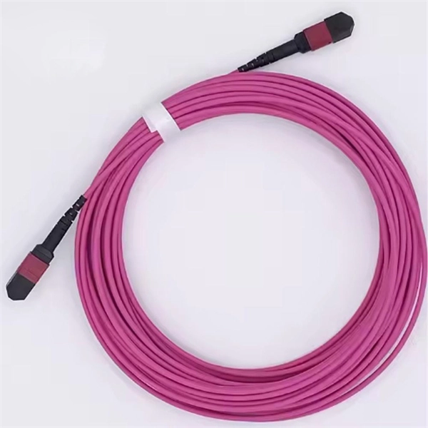
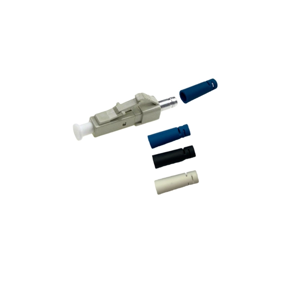
Protect fiber optic cable connections:The joint box provides physical protection for the fiber optic cable connection parts to prevent damage to the fiber optic cable caused by external environmental factors such as moisture, dust, chemical corrosion and mechanical damage. Provide a stable. Fiber optic sleeves are protective devices used for fiber optic connections. Splice protection sleeve, usually made of plastic or metal, are used to secure and protect the fusion joint between two optical fibers. Fiber Cable Joint Box is attributed to the mechanical pressure sealing joint system. Fiber Cable Joint Box is a continuous protection device for supplying optical, sealing and mechanical strength continuity between adjacent optical. The optical fiber terminal box is the terminal joint of an optical cable, one end of which is an optical cable, and the other end is a pigtail, which is equivalent to a device that splits an optical cable into a single optical fiber. The user optical cable terminal box installed on the wall, its. Fiber Optic Splice Closure is designed to protect optical fibers from debris, dirt, dust, moisture and water. As much of the fiber system is outside in a harsh environment, these fiber optic splice closures are designed to meet the tough protection requirements of fiber-optic splices. UnitekFiber. Overview Application of Optical Fiber Splice Closure/Joint Box/Joint Closure: 1. CATV environment.
[PDF]

A ladder type cable tray tee is a fitting used to create a branch in a cable tray system, allowing cables to be routed in three directions. Its "T" shape provides a secure and efficient way to split cables from a main tray into two separate paths, ensuring organized and flexible. A cable tray tee and tee cover are components used in cable management systems to support and protect electrical and data cables. Here's a brief explanation of each:. Rigid steel cable tray tee fitting with zero tangent, safety bottom, and full accessory support. ventilation to heat producing cable such as power communication and other with the same or different width of the cable run. All fittings are available in sizes and types corresponding to the straight cable tray sections. These fitting are including: elbow, horizontal cross, vertical inside. NOTE : Equal or un equal tees can be supplied. When ordering state widths W1xW2xW3.. Office: 147/22 Nguyen Sy Sach Street, 15 Ward, Tân Binh Dist, HCMC,VN. Is it possible to connect 2 cabletrays with a "branch piece (left picture)" instead of a "tee (right picture)". The tee has 3 connectors, the branch piece only has 1 connector. I would like to ajust the "Type properties -> Fittings -> Tee" with the branch family, but can't get it accomplished.
[PDF]

Complete engineering solution such as design, drawing, wiring & assembly of components onto our extensive range of enclosure We distribute from reputable and established partner manufacturers in Singapore, France, USA, Germany, India, Finland, Canada & Taiwan. Our core business is in. *Enclosure comes with base plate, sealing gasket, earthing studs and mounting accessories. *Product Specifications Subject To Changes Without Prior Notice. Sunlink Engineering designs and fabricates high-quality Metal DB Boxes (Distribution Boxes) for safe, organised, and reliable electrical distribution. Our DB boxes are widely used across industrial, commercial, marine, and infrastructure projects in Singapore and Johor, Malaysia, and are engineered. The Gustav Hensel GmbH & Co. KG is a leading company specialising in the manufacture of innovative electrical installation and power distribution systems for facility equipment of buildings. Wherever environmental influences, dust and humidity require a particularly sophisticated installation. Regional Headquarter Asia-Pacific Sales and Technical Support for Electronic and Electrical Enclosures - Cabinets NEMA 12/IP55, Subracks 19", Metric and EMC, Cases Alu, Stainless Steel, Fiberglass, Microcomputer Packaging Systems, VME Backplanes, Electrical Enclosures/Boxes, Outdoor Junction.
[PDF]