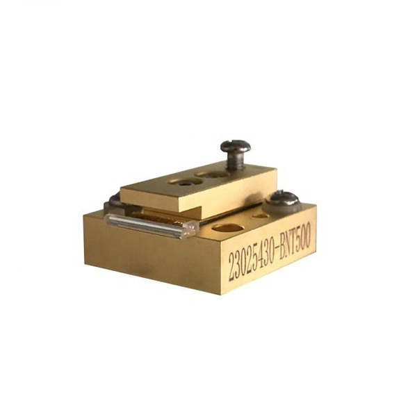
This involves achieving thermal resistance values of less than 1°C/W for high-power optical components and ensuring temperature uniformity across the package to prevent thermal gradients that could degrade system performance. Being an industry group uniting representatives of the data and optical worlds, OIF's purpose is to accelerate the deployment of interoperable, cost-effective and robust optical internetworks and their associated technologies. Optical internetworks are data networks composed of routers and data. Co-packaged optics (CPO) has emerged as an ultimate solution for achieving the ultra-high bandwidths, shoreline densities, and energy efficiencies required by future GPUs and network switches for AI. Microring modulators (MRMs) are well-suited for transmitters due to their compact size, high energy. Source: IEEE 802. 3 Beyond 400G Study Group. CPO is widely regarded as a promising. The rapid surge in global data traffic, driven by artificial intelligence and hyperscale data centers, has established copackaged optics (CPO) as a pivotal technology for next-generation high-bandwidth and low-power interconnects. Introduction The CPO JDF plans to release three documents focused on different elements of Co-Packaged Optics (CPO): the.
[PDF]
Download new and previously released drivers including support software, bios, utilities, firmware and patches for Intel products. trol I/O is desired. The Q-SYS Core 24f satisfies a broad spectrum of application needs from meeting room environments, conferencing systems, retail establishments, houses of worship, judicial environments, education institutions and other general purpose pro essing applications. A Core 24f may be. That change is why correct leads and connections matter for system stability and lifespan. Please sign in or register for an Intel account. Automatically update your drivers and software Use this tool to identify your products and get driver and. Purpose: This connector serves as the main junction, transmitting essential electrical currents from the supply unit to the motherboard. Design: It features a distinct arrangement of multiple connectors, each designated for specific functions, ensuring balanced and stable power distribution. Product replacement Get replacements and find substitutions for discontinued Schneider Electric products. Where to buy Search our network of verified distributors with over 15,000 sales outlets. Communications bus and supply power terminal blocks, functions, ratings, requirements, and cables provides information about the functions, ratings, and requirements for the communication bus and supply power terminals; and guidelines for wire sizes, cable types, and cable lengths when wiring the.
[PDF]

This guide will walk you through the process of checking photo sensors using a multimeter, covering various types of photo sensors, the necessary tools and safety precautions, and the specific measurement techniques involved. Knowing how to effectively use a multimeter to test photo sensors can save you time, money, and frustration when dealing with malfunctioning devices. more What is a Voltage Divider? | What is a Voltage. Before replacing the sensor or fixture, it's efficient testing it first, With a few tools and a step-by-step process you can find whether your outdoor lighting control system is working as intended or if the problem lies elsewhere. In this complete guide from Lead-Top, a global leader in photocell. In this blog post, we explain step-by-step how to troubleshoot a sensor with a digital multimeter (DMM). Here are the steps: Troubleshooting a sensor measurement failure requires mechanical tools to uncover the protective shields or components so you can reach the sensor in question. Always follow the manufacturer's instructions for the sensor and multimeter. Ensure the sensor is properly connected to the multimeter and. A multimeter is an indispensable diagnostic tool for anyone working with electronics, electrical systems, or indeed, sensors. It's a versatile device capable of measuring voltage, current, and resistance, providing crucial insights into the health and functionality of electrical circuits and.
[PDF]
When selecting the right fiber optic splice tray, prioritize compatibility with your cable type, secure fiber management, and ease of installation. Corning splice trays offer an easy way to store fiber optic cables and splices while protecting them from damage during fusion and mechanical splicing. The trays are engineered to use with both loose tube and tight-buffered optical cables. Their generous size and craft-friendly design help prevent. Fibre optic splicing trays are an essential part of manipulating and ordering optical fibers inside a network structure. Since the need for higher data rates and effective communication gets more robust, the utilization of optical fibers has become increasingly widespread across multiple spheres of. Optical / fiber optic 12 or 24 fiber splice tray for holding spliced fibers of fiber optic cable. For most network installations—especially in data centers or FTTH (Fiber-to-the-Home) deployments—a modular, stackable splice tray with 12 to 24 port. Discover CommScope fiber splice trays, fiber optic splice trays, and a convenient fiber splice organizer. Organize fiber connections with ease. Because optical fibers are sensitive to pulling, bending, and crushing forces, use fiber splice trays to provide secure routing and an easy-to-manage environment for fragile fiber splices. In the past, fiber optic splice trays were usually installed in a box that hung on the wall.
[PDF]
At the heart of every optical transceiver lie three essential components, often called the “Three Pillars” of optical communication: Laser — generates light. Modulator — encodes data onto the light. Photodiode — decodes light signals back into electrical form. An optical receiver is a device that converts light signals traveling through fiber optic cable back into electrical signals that electronic equipment can process. The core function of the optical receiver relies on a physical phenomenon known as photoelectric conversion. When a modulated light signal. The polarization independent isolator is made of three parts, an input birefringent wedge (with its ordinary polarization direction vertical and its extraordinary polarization direction horizontal), a Faraday rotator, and an output birefringent wedge (with its ordinary polarization direction at. Our optical receivers and detectors make photodetection easy and provide the lowest noise and cleanest response possible. Our broad offering spans wavelength ranges from UV to short-wave IR for free-space and fiber-coupled configurations in many versions: high-speed, general-purpose, balanced. Optical receivers are devices that convert light signals into electrical signals using photodetectors, which come in various types such as photodiodes and avalanche photodiodes. The document covers key concepts such as the operating principles of these detectors, noise types, signal-to-noise ratio.
[PDF]
Typically, an optical circulator consists of three main parts: wave plates, Faraday rotators, and birefringent crystals. When light enters the circulator, it is split into two beams with orthogonal polarization states. An optical circulator is a non-reciprocal device that directs light signals sequentially between multiple ports. You can think of it as a traffic controller for light, ensuring signals flow in one direction without interference. Unlike optical isolators that block reflected light, a circulator routes optical signals in a specific order — typically Port 1 → Port 2 and Port 2 →. An optical circulator is a three- or four-port optical device designed such that light entering any port exits from the next. This means that if light enters port 1 it is emitted from port 2, but if some of the emitted light is reflected back to the circulator, it does not come out of port 1 but. Optical Circulators are crucial components in modern optical communication systems, enabling the efficient routing of optical signals between different ports. In this comprehensive guide, we will explore the definition, basic principles, and importance of Optical Circulators, as well as their. The optical circulator is a fundamental device, acting as an advanced traffic controller that provides strict directional control over light signals within the network architecture.
[PDF]
This is the latest revision of this Recommendation that was first created in 1988. Recommendation ITU-T G. 654 describes the geometrical, mechanical and transmission attributes of a single-mode optical fibre and cable which has the zero-dispersion wavelength around 1300 nm wavelength, and which is loss-minimized and cut-off wavelength shifted at around the 1550 nm wavelength. The superior attributes of TXF ® optical fiber, compliant to ITU-T G. E, allow for the provision of an additional network margin that can be leveraged to enable reliable, high-data-rate transmissions over longer spans and extended reach. This allows long-haul networks with TXF fiber to be. ACOME and Sumitomo Electric have developed a new hybrid solution that allows network operators to deploy a single universal cable that supports both current and future network needs. Upgrading to 800G and above requires fewer repeaters to amplify the optical signals and can also avoid the need for. Recommendation ITU-T G.
[PDF]

Towers are not rooted by only pouring concrete—they require extensive soil analysis, wind loads, types of towers, and seismic activity to determine the necessary foundation for safety and sustainable use. A communication tower foundation design is the structural blueprint that determines the anchor point of the tower on the ground. This article delves into the intricate process of civil construction tailored. Tower owners must comply with a multi-layered regulatory, engineering, and safety framework that governs tower siting, where a cell tower can be built, how it must be designed, and how it operates throughout its lifecycle. These requirements ensure public safety, structural integrity, regulatory. Here are six foundation types for communication towers that work for a wide range of situations and environments. If you're planning a new installation, knowing the basics of these foundations can help you establish a secure and durable tower that will be a community asset for years to come. Telecom (Telecommunications) towers are a generic description of radio masts and towers built primarily to hold telecommunications antennas. As such antennas often have a large area and must be precisely pointed out, such towers have to be designed and built to limit wind induced movement. The Contractor shall employ a quality control program that will ensure that engineering, fabrication.
[PDF]
This article will focus on the failure rates of optical modules, analyze the primary causes of failure in traditional Digital Signal Processing (DSP) modules, compare failure rates utilizing LPO technology, and discuss the advantages presented by LPO modules. Linear Pluggable Optics (LPO) are a new optical transceiver technology. The idea is simple: instead of a DSP (digital signal processor) inside the module – replacing it with transimpedance amplifier (TIA) and a driver chip with high linearity and EQ capability – LPO shifts signal processing into. Copyright 2023, Coherent. Next-generation 400G and 800G modules for data centers, AI clusters, and telecoms — validated in a European lab, ready to ship from Europe. What is Low-Power Optical Transceivers (LPO)? Linear Pluggable Optics (LPO) replace the DSP inside the optical module with linear analog components, shifting. QSFP-DD LPO TRANSCEIVER DESIGNED FOR PCIE® GEN 5. 0 over optical link, enabling scalable server disaggregation and efficient rack-to-rack interconnects ideal for AI/ML and. Led by Cisco Optics experts, this MSA quickly gained broad industry support due to its vision to create cost-effective solutions for high-density multi-terabit switching, routing, and transport networks. The goal was to define optical specifications that allow for future 100G and 400G pluggable.
[PDF]

Support Portal provides access to various services for Nokia Customers and Partners, such as Product Documentation, SW Downloads, Ticket Creation and Case Handling. The latest generation of Digital Coherent Optics (DCO) pluggable transceivers represents a breakthrough in the optical networking industry. By combining advances in silicon photonics and Digital Signal Processors (DSP) with Quad Small Form-factor Pluggable – Double Density (QSFP-DD) form factor. Ciena's WaveLogic 6 Extreme 1. 6T quantum-safe encryption solution on the Waveserver platform was designed with this in mind, supporting QKD system interworking and NIST-certified PQC algorithms. It delivers an always-on, wire-speed encryption solution, without impacting performance or adding. 400 Gigabit Ethernet (400G) transceivers are optical modules capable of handling data rates of 400 Gbps. With a transmission rate of up to 400 Gbps, 400G transceivers offer double the capacity of their predecessor (200G transceivers). 400G. ONU, or Optical Network Unit, is a networking device that connects your home or business to the internet using fiber optic cables. It's like a bridge between the vast internet world and your personal network. ONU is a small device that sits somewhere in your house. When you connect your computer. C-Data's ONU products include models that offer data, data + voice, data + CATV, and Triple Play services. They support TR-069 and provide excellent compatibility with third-party OLT systems.
[PDF]