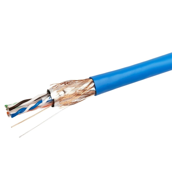
The number of optical cores in an optical fiber is the total number of equipment interfaces multiplied by 2, plus 10% to 20% of the spare quantity, and if the communication mode of the equipment has serial communication and equipment multiplexing, you can reduce the number of cores. A fiber optic cable typically has multiple cores, depending on its design and purpose. The most common type of fiber optic cable used in telecommunications is single-mode fiber, which usually has a single core. This post will guide you through understanding fiber optic cores and selecting the perfect cable for your needs. Understanding Fiber Cores: Core: The central glass fiber that transmits light signals. Single-mode: A. The total number of cores for a 1pc fiber patch cable is calculated as the number of branches multiplied by the number of cores per branch (if there are no branches, the number of branches = 1). The number of. This guide walks you through the simple decision steps engineers use, the common strand counts on the market, and clear rules-of-thumb for different project types so you choose a cable that fits both today's needs and tomorrow's growth. Begin by listing what the network must support now and in five. Fiber optic cables are used to transmit data and audio signals using light. They come in different types, each designed for specific applications and distances.
[PDF]
Please select a category, brand, and model to find a type-approved device. Results will be displayed here after search. You can now apply and manage your RSB services online. Start today! The RSB Standards Store has a wide range of Standards covering various sectors and industries. Need help with any of your other applications? Apply for Zamukana Ubuziranenge and get assistance from our staff. Increase the. An LPO (Linear Pluggable Optics) solution offers considerable power savings for optical interconnect by removing the digital signal processing (DSP) function from the pluggable optical module. The idea is simple: instead of a DSP (digital signal processor) inside the module – replacing it with transimpedance amplifier (TIA) and a driver chip with high linearity and EQ capability – LPO shifts signal processing into. LPO (Linear-drive Pluggable Optics) is a transceiver packaging technology. It utilizes specialized components, including ASIC substrates, ASIC. In response, several solutions such as Linear Receive Optics (LRO), Linear Pluggable Optics (LPO) and Co-Packaged Optics (CPO) have been proposed. 1 shows the typical block diagram of a pluggable transceiver consisting of on-board lasers, optics, a Photonics die housing the modulator.
[PDF]
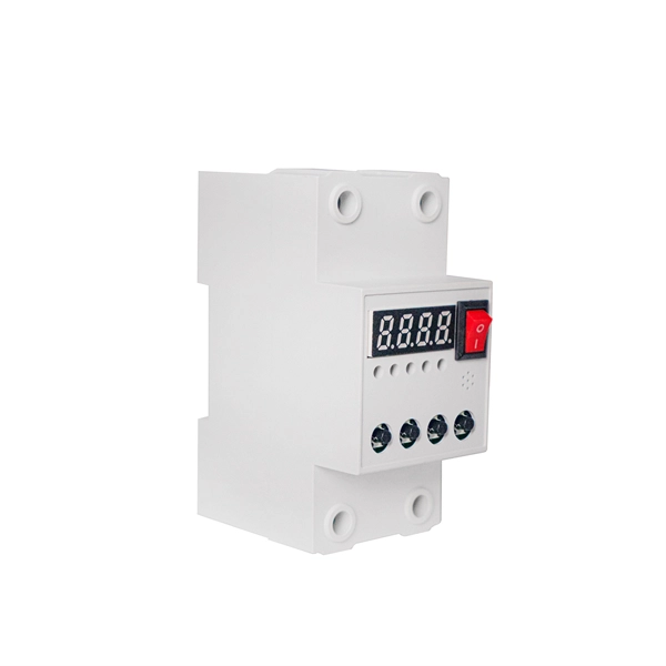
Connectorized attenuators often have a quite compact housing, essentially looking like a fiber-optic adapter. Some of these devices provide a fixed level of attenuation, quantified as the insertion loss in decibels. An optical attenuator, or fiber optic attenuator, is a device used to reduce the power level of an optical signal, either in free space or in an optical fiber. The basic types of optical attenuators are fixed, step-wise variable, and continuously variable. Optical attenuators are commonly used in. Fiber-optic attenuators are a specific type of optical attenuators which are used in fiber optics, e. for achieving a suitable signal level for a data receiver in a telecom system. It primarily ensures the power or amplitude of a signal is lowered without significantly distorting its waveform. The attenuator circuit will allow a known source of power to be reduced by a predetermined factor, which is usually expressed as decibels.
[PDF]
We have identified 63 global optical fibre cable tenders from the public procurement domain worldwide. View the latest global tenders for optical fibre cable from Africa, the Americas, Asia, Australia, Europe, the Middle East, and other countries. Recently, China Mobile's centralized procurement results of ordinary optical cables from 2021 to 2022 have been released. 2 million core kilometers). Compared. Find RFP searches and finds fiber optics bids, contracts, and request for proposals. Below is a sample search result showing the newly published government contracts and bids in fiber optics, cabling, wiring. These include government RFPs, RFTs, RFIs, RFQs in fiber optics from federal, state, and. China Mobile released details regarding the awards of their 2025/2026 loose-tube optical cable tender on 7 June 2025 – less than one month after announcing the tender on 8 May 2025. As anticipated, competition for the 98. 8M F-km optical cable tender was intense. 654E optical fiber and cable product centralized procurement project have been implemented, and the procurement conditions have been met, and now public. The Bid For China Mobile Ordinary Optical Cables Central Procurement (2021-2022) Of 9 Billion Yuan Won By YOFC And Other 14 Companies Today, China Mobile announced the results of centralized procurement of ordinary optical cable products from 2021 to 2022.
[PDF]
Average import price for QSFP under HS Code 85176290 was $2,193. Please use filters at the bottom of the page to view and select unit type. There are 58 exporters of QSFP. 400G QSFP-DD Transceiver, 400GBASE-DR4, MPO-12,500m parallel. This information is derived from data obtained from. FS provides an expanding portfolio of 400G OSFP/QSFP112/QSFP-DD solutions featuring high-performance, high-bandwidth, and backward compatibility. The 400G transceiver modules are ideal choice for AI data centers, enterprise networks and service provider networks. Click to get your 400G transceiver. The QSFP-DD DCO 400ZR+ coherent module is capable of transmitting 400 Gbps over 120 km with excellent OSNR and power consumption in OIF 400ZR implementation protocol and QSFP-DD MSA-compliant designs. Utilizing the latest in-house Sipho Coherent Optical Assemblies (COSA) and nano-ITLA, the module. Quad Small Form-factor Pluggable Double Density (QSFP-DD) solution that fits into high-density switch and router client ports for optical interconnect links Powered by Greylock and Delphi DSP ASICs, and silicon photonic integrated circuits (PICs) for an optimized co-packaged design with 3D. OIF 400ZR, Standard Tx output power (-10dBm), C-band tunable, Pull tab, 0°C to 70°C, LC receptacle. Reconfigurable optical add/drop multiplexers (ROADMs) in existing and emerging DWDM transport networks require a high optical launch power (0 dBm) and high transmit in-band and out-of-band optical.
[PDF]

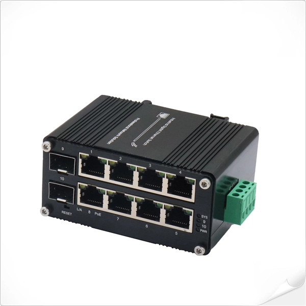
Source over 605 fiber-optic modules for sale from manufacturers with factory direct prices, high quality & fast shipping. FS provides 1/2/4G transceivers modules in SFP form factor, supporting transmission distances from 100m to 120km over SMF/MMF fiber and enabling low power and cost-effective connectivity solutions. Purchase from nearby warehouses. Trusted by 260K+ Enterprise Users. Fiber optic transceiver modules are fiber cable adaptive housings that contain a light source for transmitting data via fiber optic cable as well as a photodiode for receiving fiber optic data. Mounting options include pluggable CXP, QSFP, SFF, SFP, and XFP, surface or through-hole, CFP, 1x9 SC. This article covers both custom optical elements and custom optical assemblies or systems — beginning with the former. Many optical elements such as lenses, laser mirrors, prisms and diffraction gratings are fabricated as standard parts, i., they are made with the same specifications for many. $ 3,869. 00 Original price was: $3,869. Sale! Sale! Sale! Sale! $ 369. 00 Original price was:. Edmund Optics ® manufactures and supplies customers around the globe with millions of precision optical components and optical assemblies. Our manufacturing capabilities comprise of expertise and resources necessary to manufacture optical products based on your project's specific requirements. Our. TAKFLY COMMUNICATIONS CO. Fiber optical modules Humpal SFP module.
[PDF]

Wavelength measurement devices work on the principle of measuring the distance between two consecutive points of an electromagnetic wave in terms of wavelengths. This can be achieved through various methods, including spectrophotometry, interferometry, or the use of optical spectrum. These devices accurately determine the wavelength of light, providing crucial information for research, quality control, and diagnostics. Wavelength is a fundamental property of light and can significantly affect its interaction with matter. Precise wavelength measurement allows scientists to. Wavelength meters are interferometers used to measure wavelengths of laser beams. The devices are mounted on benches or desktops. They generate numerical values identifying pulsed and continuous wave lasers. They enable. This article provides a comprehensive explanation of the concept of wavelength in physics, particularly in optics and photonics. It defines wavelength as the spatial period of a wave, explaining its mathematical relationship to the wavenumber, optical frequency, and phase velocity. Accurate wavelength measurement is crucial in fields like physics, chemistry, astronomy, and engineering. Each method offers unique insights and varying degrees of precision.
[PDF]

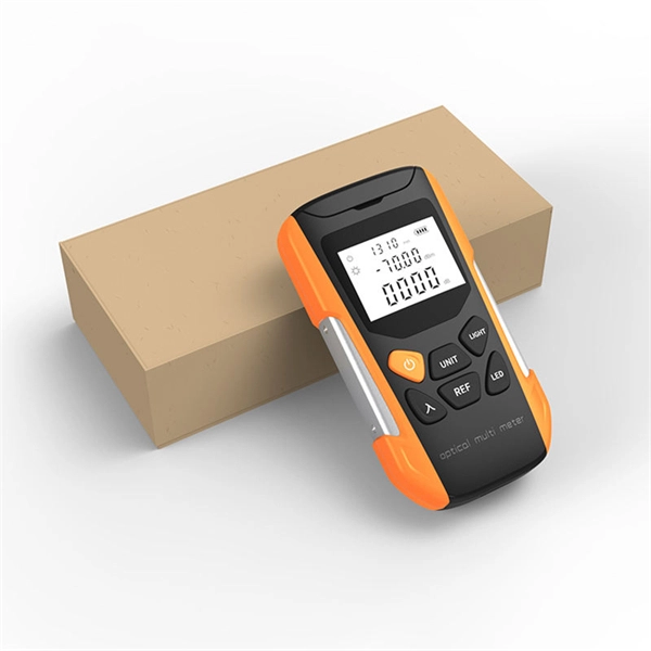
To use a power meter for fiber optic testing, always clean connectors first with lint-free wipes or click-to-clean tools. Select the correct wavelength and set your reference. You measure optical power in dBm or insertion loss in dB. Consistent procedures ensure accuracy. Verify light travels from. The most basic fiber optic measurement is optical power from the end of a fiber. This measurement is the basis for loss measurements as well as the power from a source or presented at a receiver. Typically both transmitters and receivers have receptacles for fiber optic connectors, so measuring the. An optical power meter measures the strength of light traveling through a fiber optic cable, giving you a reading in dBm (decibels relative to one milliwatt). This article will guide you through the methods, instruments, and key considerations for measuring fiber. Fiber optic cabling is the high-performance core of today's datacom networks. As network speeds and bandwidth demands increase, fiber performance requirements have become more stringent. Fiber testing is more important than ever. An OPM uses a photodiode to generate an electrical current proportional to optical power.
[PDF]
Langzhi China is a professional FTTH equipment manufacturer specializing in GPON/EPON OLT, ONU/ONT, and SFP modules compatible with Huawei & ZTE. Factory-direct pricing, global shipping, OEM/ODM available. Shop now for reliable fiber optic network solutions. Hengtong Group was established in 1991 and is the largest optical cable manufacturer in China. They are committed to the development of comprehensive cabling systems and have established a complete optical communication product chain, from optical fiber to fiber optic cables to optical devices. We will analyze the. Fiberlink is a professional fiber optic cable manufacturer, producing over 20,000 fiber optic products annually and offering a wide range of solutions, including connectors, patch cords, and cabling systems. With ISO9001 certification and a dedicated engineering team, Fiberlink positions itself as. Here are the top-ranked fiber optic cable companies as of May, 2026: 1. Charlton Precision Products, Inc. WIN SOURCE ELECTRONICS, 3. Megladon Manufacturing Group, Ltd. This guide ranks China's top 10 fiber optic cable manufacturers for 2025, based on market share, production capacity, innovation, and global reach. The list prioritizes companies with strong export performance (to 100+ countries) and compliance with international standards like ITU-T G.
[PDF]

Attenuation describes the continuous loss along the fiber, while insertion loss describes the additional loss caused by components such as connectors, splices, or splitters. In fiber optic networks, particularly in FTTx (Fiber to the x) and PON (Passive Optical Networks) deployments, splitters play a central role in distributing the optical signal from a single source to multiple destinations. The split ratio and insertion loss are two key parameters defining their performance. A deeper understanding of these. This document describes how to calculate the maximum attenuation for an optical fiber. You can apply this methodology to all types of optical fibers in order to estimate the maximum distance that optical systems use. There are no specific requirements for this document. This document is not. By dividing a single optical signal from a central Optical Line Terminal (OLT) into multiple outputs for Optical Network Terminals (ONTs) at users' homes, splitters eliminate the need for dedicated fibers to each residence—slashing infrastructure costs while scaling network reach. Losses can be introduced by various means such as intrinsic material absorption, scattering, bending, connector loss and more. The tutorial has the following parts: When light propagates as a guided wave in a fiber core, it experiences some power losses. These are particularly important for long-haul data transmission through fiber-optic telecom.
[PDF]

As fiber optic cables are generally only produced in lengths up to around 5 km, so when lengthier connections are needed, splicing two cables together becomes necessary. So in essence, fiber optic splicing is a process used to join two separate fiber optic cables together. There are numerous use cases for fiber optic splicing. As. The time it takes to splice a fiber optic cable can vary depending on several factors, including the type of splice, the equipment used, and the level of expertise of the technician performing the splice. Proper termination is essential for ensuring optimal performance, reducing signal loss, and maintaining the durability of the connection. Another method of connecting optical fibers is termination or connectorization, which consists of processing the end of a fiber optic bundle so that it can be connected to other fibers or devices through fiber optic. Fiber optic joints or terminations are made two ways: 1) splices which create a permanent joint between the two fibers or 2) connectors that mate two fibers to create a temporary joint and/or connect the fiber to a piece of network gear. Either joining method must have three primary characteristics.
[PDF]

Regularly testing fiber optic cables helps minimize network downtime, lengthens the network's longevity, reduces maintenance requirements, and helps support network reconfiguration and upgrades. Fiber optic testing ensures the performance and reliability of fiber optic networks. Key tests include: Effective fiber testing utilizes advanced tools such as Optical. Fiber optic testing for continuity is crucial in ensuring that light transmits through fiber optic cables without interruptions, safeguarding seamless data transmission. This guide talks about the primary methods and tools for effective continuity testing in fiber optic cable networks. Insertion loss testing confirms whether the cable meets design loss budgets. OTDR testing identifies events along the fiber length, including: OTDR is essential for long-distance FTTH feeder and distribution cables. After the cables are installed and terminated, it's time for testing. For every fiber optic cable plant, you will need to test for continuity, end-to-end loss and then troubleshoot the problems. If it's a long outside plant cable with intermediate splices, you will probably want to verify the. We'll explain why it's vital to test fiber optic cables, the three most popular methods, and when you should use them. Why Testing Fiber Optic Cables Matters? Regular testing of fiber optic cables is not just a preventive measure; it's an.
[PDF]
Indoor cable (PVC or LSZH jacket) is cheaper but unsuitable for wet or UV-exposed environments. Fiber optic cables are essential components in today's broadband, FTTx, and data center networks. Whether you're planning a national fiber rollout or sourcing cables for enterprise infrastructure, understanding how fiber optic cable pricing works can help you budget more effectively and make better. Buyers typically pay for fiber optic cable by length, fiber type, and installation complexity. Main cost drivers include cable grade (indoor vs outdoor, armoured), distance, and labor for trenching, splicing, and termination. This guide presents ranges in USD and practical price estimates to help. Optic cable price represents a crucial consideration in modern telecommunications infrastructure, reflecting the complex interplay of manufacturing costs, technological advancement, and market demand. These essential components of digital communication networks vary in price based on several key. * Disclaimer: Prices fluctuate based on raw material indices (Glass/Copper/Polymer) and cable core count (e. This feature makes them ideal for high-voltage power lines where both grounding and data transmission are needed. On the other hand, standard fiber optic cables 4 focus solely on data transmission and are.
[PDF]
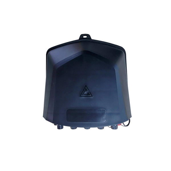
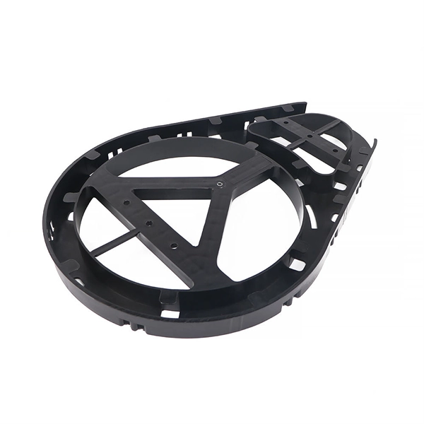
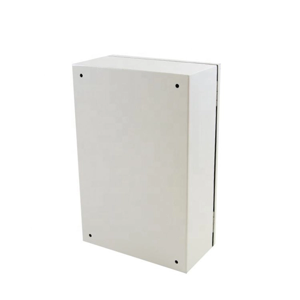
An optical junction box is a vital component in fiber optic networks. It serves as a termination point for fiber optic cables, providing protection and distribution of the optical fibers while ensuring efficient signal transmission. Optical cable junction boxes play a crucial role in connecting and protecting optical fibers, directly influencing the quality and lifespan of optical cable routes. As the demand for high-speed internet and reliable telecommunications increases, the. What is an optical cable splice box Optical cable splice box is a popular name, its scientific name is optical cable splicing box, also known as optical cable splicing package, optical cable splicing package and gun barrel. It belongs to the mechanical pressure sealing joint system and is a splice. --- Optical Fibre Junction Boxes are critical components in the realm of telecommunications, serving as the interfacing point for optical networks.
[PDF]
In the photopic region, luminous efficacy peaks at 683 lumens per watt at 555 nm. In fact, the lumen is defined in terms of the power at 555 nm (frequency of 540 × 1012 Hz). Luminous efficacy is defined as the luminous flux produced per unit of power, usually electrical power, measured in lumen per watt (lm/W). It is explained how the overall efficacy of a lighting installation is often lower than that of the light source itself due to factors like light absorption in. Luminous efficacy is a measure of how efficiently a light source produces visible light. Depending on context, the power can be either the radiant flux of the source's output, or it can. The relative spectral responsivity of the human visual system was first defined by the Commission Internationale de l'Éclairage (CIE, the International Commission on Illumination) in 1924. The response of the eye as a function of frequency is called the luminous efficacy of the eye. It has been tabulated for both the light-adapted (photopic) case and the dark-adapted (scotopic) case. Source: Table 6-1 of.
[PDF]

