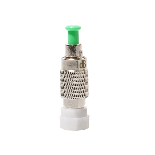
Diagram showing positive tip polarity on the left and negative tip polarity on the right. To read diagram: The center positive drawing on the left indicates that the center (also known as the tip) of the output plug is positive (+) and the barrel (ring) of the output plug is negative. The center positive drawing on the left indicates that the center (tip) of the output plug is positive (+) and the barrel of the output plug is negative (-). Symbol for a center-positive power supply. It is always good practice to test. The term positive terminal describes which of the two connection terminals on direct current (DC) equipment supplies or is meant to receive a positive electrical charge. DC power supplies always feature a positive to negative electron flow and always have a negative and positive terminal. Polarity. It is defined by the positive and negative terminals of a power source, such as a battery. Understanding polarity is essential because connecting a device to a power source with the correct. The rating plate of an Extra Low Voltage Power Supply (ELVPSU) shows various symbols and abbreviations. These represent critical information about the supply's ratings, class, polarity, and other safety details. The polarity symbol indicates if the centre (or tip) of the output plug is positive (+).
[PDF]
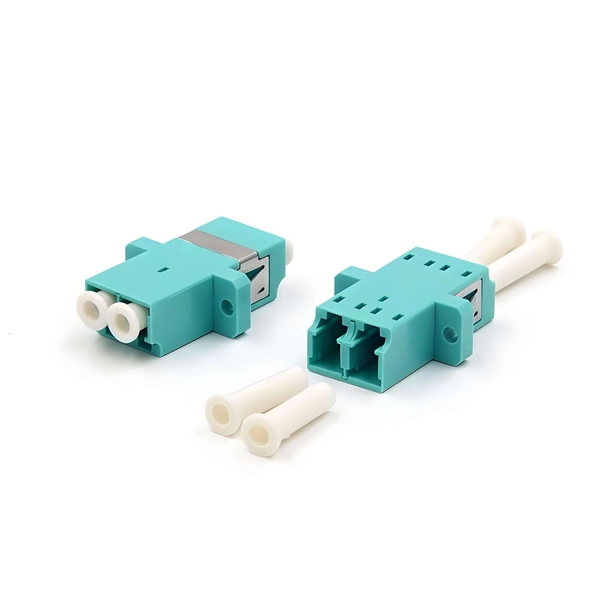
LC pigtails are short fiber optic cables which have one connector on their one end and a bare fiber on the other. The connector type most commonly used is the LC connector, known for its compact size and ease of use. It is usually suitable for field termination using a mechanical or fusion splicer. Compared with quick termination or epoxy and polish connections placed on the field. The optical fiber connector is a kind of detachable passive optical component used in the connection between fiber to fiber, the light source to the fiber, and fiber to the detector to achieve the light maximize coupling to the receiving fiber. According to the estimating, there are hundreds of. HOLIGHT fiber pigtails ensure low-loss termination. Available in SC, LC, FC, ST, singlemode & multimode for precise splicing. LC pigtails come in simplex (single fiber) or duplex (two fibers) configurations. Executive Summary: A fiber optic pigtail is one of the most commonly specified yet least understood components in structured cabling. Get the wrong connector type, the wrong polish, or skip proper fusion splicing technique—and you're looking at elevated signal loss, increased back reflection, and a. Fiber optic pigtail has an optical connector pre-installed on one end and a length of exposed fiber at the other end. LC series pigtail normally comes with 0. 9mm cable diameter, UPC/PC and APC versions, SM, MM, OM3 and OM4 modes. 5 meter, also can be as customer's.
[PDF]

It consists of 5 buttons. A power button, a button to turn on the VFL, a lambda button to set the wavelendth, a REF button, and a dBm/W button to set the unit of power. First, you check the initial power of a light signal. Then you check its power at the other end of optical. OPM interface: insert the fiber to be tested, test the optical power. REF/dB key: Short press the dB to switch unit, click once nW/dBm/dB to enter the upper clear data, press and hold until REF is displayed on the screen, and set the current optical power as reference value, enter the relative. There are two buttons on this meter. One is the power button, used to turn the meter on/off. At the top, there is a sensor that detects the light beam. The. at -22 (or 25 with tone on)). To do this you. Active Equipment Power Measurement Fiber Continuity Patch Cable Testing Check MM Reference Cables - Dual OWL MM Sources Check MM Reference Cables - WaveSource MM Sources Check SM Reference Cables - Laser OWL SM Sources Check SM Reference Cables - WaveSource SM Sources. Power-off: Press and hold “MODE” key for 2 seconds or more until “OFF” displays on the screen. Note: This instrument will shut down automatically without receiving any operation instruction for 10 minutes. Function selections: It.
[PDF]

PDH called Parallel Data Highway, is a quasi-synchronous transmission technology based on digital transmission. PDH defines multiple multiplexing levels, such as 2Mbps (E1), 8Mbps (E1). This page defines various terms related to the optical domain. It covers SDH, PDH, SONET, DWDM, FTTH, WDM, PDMA, wavelength converters, optical ADMs, EDFAs, and SOAs. Converts optical light from one wavelength to another. Definitions of common terms related to fibre optics, including SDH, PDH. Part I. SDH is a synchronous TDM technology that multiplexes low-order signals into high-order signals. Because the entire network is. PDH (Plesiochronous Digital Hierarchy), is an early digital transmission standard to handle the transport of digital signals over copper and fiber-optic networks. It appeared in the 1980s and developed rapidly. PDH, in the form of traditional point-to-point connection of various media. The term "plesiochronous" refers to the fact that PDH operates with nearly synchronized timing between. The method was developed to replace the plesiochronous digital hierarchy (PDH) system for transporting large amounts of telephone calls and data traffic over the same fiber without the problems of synchronization. SONET and SDH, which are essentially the same, were originally designed to transport.
[PDF]

A beamsplitter is a common optical component that partially transmits and partially reflects an incident light beam, usually in unequal proportions. In addition to the task of dividing light, beamsplitters can be employed to recombine two separate light beams or images into a single. Beamsplitters are fundamental components in optical engineering, serving to precisely divide a single input beam of light into two distinct output beams. This division allows for the simultaneous analysis or utilization of the light's properties along two separate paths. It is a crucial part of many optical experimental and measurement systems, such as interferometers, also finding widespread application in fibre optic telecommunications. a laser beam) into two (or sometimes more) beams, which may or may not have the same optical power (radiant flux). Different types of beam splitters exist, as described in the. The beam splitter splits and then recombines infrared radiation, while the detector picks up the resulting signal. It's sensitive to both intensity and frequency. Together, they decide just how accurately an instrument captures those unique infrared “fingerprints” from different substances.
[PDF]
The most efficient way to terminate a fiber run is by using a pigtail. A fiber pigtail is a short length of optical fiber that comes with a high-quality, factory-polished connector already installed on one end, leaving a length of exposed glass on the other. Instead of building a connector from. Installing fiber optic pigtails correctly is essential for ensuring low signal loss and long-term reliability. Remove the outer coating carefully to expose the fiber. Use alcohol wipes to remove dust and debris. Make a precise cut for optimal splicing. Align and fuse the pigtail fiber with the main. Executive Summary: A fiber optic pigtail is one of the most commonly specified yet least understood components in structured cabling. Get the wrong connector type, the wrong polish, or skip proper fusion splicing technique—and you're looking at elevated signal loss, increased back reflection, and a. A fiber optic pigtail is a short length of optical fiber with a connector pre-attached to one end. If you're new to fiber optics or want to enhance your technical skills, this guide will help you understand how to splice fiber pigtails safely and efficiently. --- 🔧 In. Fusion splicing involves precisely melting the ends of two optical fibers together, creating a seamless connection that minimizes signal loss. This method offers the lowest attenuation and reflectance, making it ideal for long-haul telecommunications. You can buy this fusion splicing kit here On.
[PDF]
A junction box contains two trade size 3 raceways on the left side and one trade size 3 raceway on the right side. raceway on the right side, and one 3-in. raceways on. Pull boxes, junction boxes, and conduit bodies must be sized to allow conductors 4 AWG and larger to be installed without damage to the conductor insulation. The NEC provides sizing requirements in 314. Keep in mind these requirements address conductors used for general wiring, such as those. Article 370 covers the installation and use of all boxes (and conduit bodies) used as outlet, junction, or pull boxes, depending on their use. You're reading an older article from ELECTRICAL CONTRACTOR. Some content, such as code-related information, may be outdated. Visit our homepage to view the. When conductors enter an enclosure with a removable cover, such as a conduit body or wireway, the minimum distance from the raceway entry to the removable cover is the bending distance listed in Table 312. 6 (A) for one conductor per terminal [314. This approach helps in the safe organization of wires. To stop a fire from beginning or spreading, sparks are contained by fireproof connections and boxes. In this reading, we will delve into the definition of a. For example, a box is needed for eight 2-inch conduits. Each conduit will contain 2/0 conductors that will be spliced within the box. What is the minimum length required for the left/right (“X”) dimension? The minimum distance required because of the.
[PDF]