will introduce major upgrades to its Multi-Rail technology platform at ECOC 2025, targeting hyperscale optical transport with new efficiency, scale, and performance enhancements. Coherent Corp. SAXONBURG, PA, September 26, 2025 (GLOBE NEWSWIRE) – Coherent Corp. At the heart of the. SAXONBURG, Pa. At the heart of the. Simultaneously, coherent technology has emerged as the prevailing solution for Data Center Interconnection (DCI) applications, covering distances of 80~120km in the field of data communication. These evolving applications introduce new demands for coherent optical transceiver systems, steering the. Coherent optical module refers to a typically hot-pluggable coherent optical transceiver that uses coherent modulation (BPSK / QPSK / QAM) rather than amplitude modulation (RZ/ NRZ / PAM4) and is typically used in high-bandwidth data communications applications. Optical modules typically have an.
[PDF]

The video tutorial demonstrates the depin and repin method for repairing automotive wiring harness connectors, specifically pigtails. It outlines seven easy steps to replace a pigtail connector, making it accessible for DIY enthusiasts and individuals dealing with electrical issues. This comprehensive guide will equip you with the knowledge and skills to accurately assess the integrity of a pigtail, helping you identify issues before they escalate into larger problems. We'll explore different testing methods, delve into the interpretation of multimeter readings, and offer. The latest in the line of Ford Flex Probe Kits, this newest release includes all the probes from the previous “D” kit, but now adds two each of the Micro Pin (. Additionally, all probes will now be printed with the tip size, helping technicians ensure usage of the properly sized tip. Short answer: An automotive wiring pigtail is a short section of wire with a pre-attached connector that lets you repair or replace a damaged plug without replacing the entire harness. It provides a plug-and-play repair solution that restores OEM fit, seal, and electrical reliability. Key steps. At FindPigtails. com, we specialize in high-quality, OEM connector replacement. Why pay thousands for a complete wire harness, when you can simply replace the damaged connector? We invite you to take a look at some of our instructional videos, for step-by-step guides of de-pin and re-pin procedures.
[PDF]
Fiber optic couplers can either be passive or active devices. Passivefiber optic couplers are said to be passive as no power is required for operation. They are simple fiber optic components that are used to re.
[PDF]
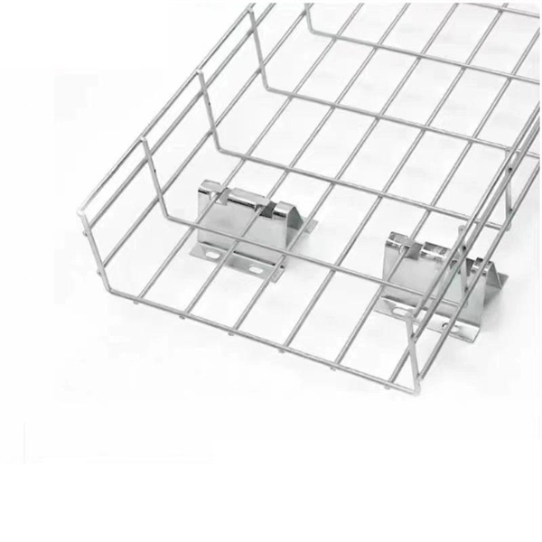
A cable tray system supports and protects both power and signal cables and facilitates upgrading, expanding, reconfiguring, or relocating networks. Most of these systems are open, allowing efficient heat dissipation and easy access for replacement and repairs. This is the role of the cable tray system—a structured framework designed to support and organize insulated electrical cables, control cables, and communication lines. Far superior to traditional conduit in many applications, cable tray systems offer unparalleled accessibility for maintenance. In this guide, we explain what cable trays are, the main types available, how to choose the correct size and duty rating, and what to consider when designing a cable tray installation. There are several types of cable trays, including ladder, perforated, solid bottom, basket, and channel trays. Each cable tray type performs a different function and comes in various materials such as aluminum. Cable trays are components of support systems for power and communications cables and wires. They provide a safe and reliable way to manage the complex network of cables that run throughout buildings, data. Industrial electric cable trays, are fundamental to ensuring a safe and organized installation of electrical systems. These support systems are used to organize electrical cables inside industrial, commercial, and residential buildings and play an important role in making sure cables are protected.
[PDF]
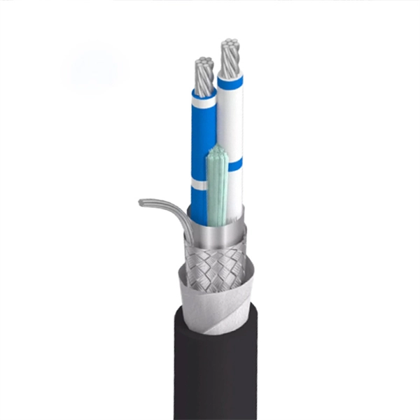
Discover the most common types and models of Direct Attach Cables (DACs), including 10G, 25G, 40G, 100G, 200G, and 400G. A Direct Attach Cable (DAC) is a factory-assembled high-speed copper cable with fixed connector “module-style” ends. It's widely used for short-reach links in data centers because it delivers low latency, simple deployment, and cost-efficient interconnects-especially for rack-level connectivity. These cables come pre-terminated with SFP (Small Form-factor Pluggable) or QSFP (Quad Small Form-factor Pluggable) connectors which simplify network setup. High-speed cable is a kind of low-cost short-distance connection solution to replace optical modules. Both of its ends have cable assemblies of a module, which are connected. Direct attach copper (DAC) cables are twinax copper assemblies with fixed transceiver-like ends. They deliver high bandwidth, low latency, and great density for top-of-rack (ToR), server-to-switch and switch-to-switch connections. This article summarizes the common DAC categories and. What is a Direct Attach Copper (DAC) Cable? Common Types And Uses Summary : Direct Attach Copper (DAC) cables provide fast, reliable, and cost-effective short-distance connections for data centers, enterprise networks, and top-of-rack setups. With passive and active variants, DAC cables offer.
[PDF]

There are many types of protective relays, and each one is designed for a specific type of protection. Common types include overcurrent relay, differential relay, distance relay, earth fault relay, and under/over voltage relay. Protective Relay Definition: A protective relay is an automatic device that senses abnormal conditions in electrical circuits and triggers actions to isolate faults. HT panel protection relay. The HT power supply is received from GO switch and distributed to the. Provides protection, logic, and metering All-in-one solution. Combines protection, sensors, control power, and circuit breaker in a single package Typically added to a breaker close circuit to prevent accidental reclosure after a trip. Three fundamental components required for each circuit breaker. Its main purpose is to safeguard electrical equipment like transformers, generators, and transmission lines from damage due to. There are different types of relays available and each type is used based on the requirement. So this article discusses an overview of a protective relay or protection relay – working with applications.
[PDF]

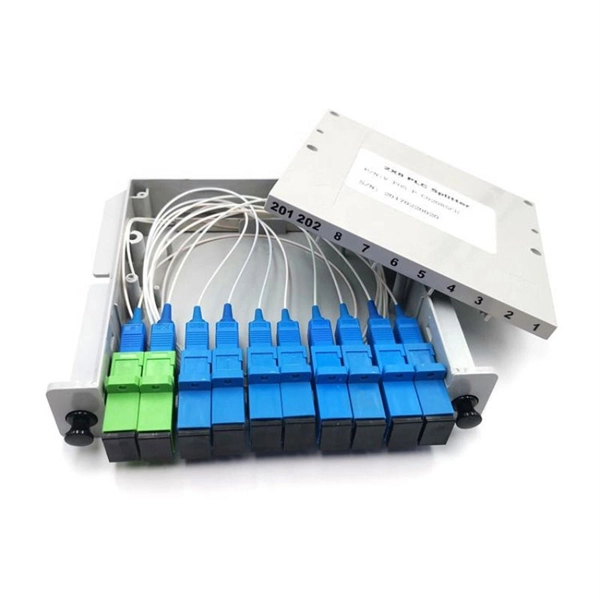
There are two main types of optical splitters based on manufacturing techniques: Fused Biconic Taper (FBT) splitter and Planar Lightwave Circuit (PLC) splitter. Optical splitters and couplers split or combine light—distributing signals injected into a single fiber strand to multiple fibers, enabling point to multi-point communication in Fiber To The Home (FTTH) networks based on ITU. T PON standards such as GPON, XGS-PON and new 25 and 50G standards. Optical splitters, also known as fiber optic splitters, are integral components in fiber optic networks, enabling one fiber input to be divided into multiple outputs. This capability is crucial in telecommunications, especially in Passive Optical Networks (PONs), where fiber-optic networks must. FS PLC Fiber Optic Splitters, Bare/Blockless/ABS/LGX Splitter/Rack Mount Types, support 1xN light distribution, with low IL and PDL for high-reliability transmission. Deploying compact FS PLC Splitters to simplify your networks, perfectly fits your PON, EPON, FTTX, etc. Conversely, it can also combine multiple signals into one. Unlike active devices (which require power), splitters operate without electricity, relying solely on the physics of. Fiber optic splitter is a passive optical device used to distribute optical signals, which can divide input optical signals into multiple outputs to meet the fiber optic access needs of multiple terminal devices.
[PDF]

This guide explains how to make 90° bends, vertical bends, tees, and offsets in wire mesh cable trays safely and professionally. Horizontal 90° Bend (Flat Bend) 2. Tee (T-Junction) Bend 4. Since the jaws of the bolt cutter drags a layer of zinc across the cut end and forms a protective layer. When a wire cable tray is cut, the fact that a. Wire mesh cable trays are widely used because of their flexibility and easy on-site modification. Unlike perforated trays, bends can be created directly at site without expensive fittings. Great if you are new or just forgot how to do it, this easy to follow guide makes it so simple. more The Easy Guide to. This involves a few essential steps to ensure a successful bending process. The first step in preparing the. The method for producing bridge bend elbows is as follows: Take a 90-degree cable tray bend elbow as an example, and apply the same principles for 45-degree bends accordingly. The length of the bottom side (bottom diagonal) after bending the cable tray should be equal to the width of the cable. OTHER THAN 90 ̊ JUNCTIONS Use this guide to learn the most effective installation practices when installing Cablofil tray. Each example of bends and tee's clearly illustrate proper tray cutting combined with recommended usage of Cablofil accessories. Engineers and contractors in North America and.
[PDF]
There are connectors designed for single mode and multimode fiber optic cables, which differ in core size, bandwidth, and optimal use cases as explained in this comprehensive guide to fiber optic cable.
[PDF]
There are two main types of RF attenuators: fixed and variable. Fixed Attenuators: Provide a fixed amount of attenuation, typically designed using discrete or chip resistors. These can be further divided into:. Attenuators are designed to change the magnitude of the input signal seen at the input stage, while presenting a constant impedance on all ranges at the attenuator input. A compensated RC attenuator is required to attenuate all frequencies equally. Without this compensation, HF signal measurements. Let's look at the common types of attenuators Fixed attenuators, as their name suggests, are fixed or unchanging. These are used in applications that don't require changing levels of attenuation or where an occasional replacement of one attenuator with another is acceptable. Say we now add a 6 dB pad between. An RF Attenuator is a two-port passive electronic device designed to reduce (attenuate) the power or amplitude of an RF signal. They can adjust the signal strength by controlling the amount of attenuation, ensuring that the signal reaches the desired level for transmission in a.
[PDF]
Fixed fiber optic attenuators are used to reduce the optical power signal in communication links. They work analogous to a step-down transformer. As the signal approaches a device or node in a communication link the power is reduced to a level that is suitable for its application. They are used to control the power level of optical signals at the outputs of light sources and electrical-to-optical (E/O) converters. Measured in decibels (dB), loss degrades signal quality, limits distance, increases bit-error rate, and escalates infrastructure cost. Understanding and managing it is critical to. The Fiber optic attenuator is an optical device that reduces the energy of the optical signal—used to attenuate the input optical power to avoid the distortion of the optical receiver due to the input optical power being too strong. It works by dissipating a portion of the optical power passing through it, thereby lowering the overall power level. Fiber optic attenuators.
[PDF]

This guide on how to fix router red light, will walk you through the common reasons behind the red light and provide step-by-step solutions to bring your router back online. A red light on your router can be a source of frustration and confusion. It often indicates that something is wrong with your internet connection or the device itself. Fortunately, diagnosing and resolving these issues doesn't have to be complicated. You might feel like you're staring into the abyss of digital darkness, wondering what went wrong. But don't despair! This guide will walk you through the most common causes of router. Experiencing a solid red broadband light on your router can be frustrating and indicates a disruption in your internet connection. Understanding the possible causes and fixes for this issue is crucial to getting your connection back on track. Here are some steps you can take. The following article will explain why the Internet is light red and what you need to do to fix it. What does it mean by Internet Light Red On Router? Our router's lights are.
[PDF]
A beam splitter or beamsplitter is an optical device that splits a beam of light into a transmitted and a reflected beam. It is a crucial part of many optical experimental and measurement systems, such as interferometers, also finding widespread application in fibre optic telecommunications. DesignsIn its most common form, a cube, a beam splitter is made from two triangular glass which are glued together at their base using polyester,, or urethane-based adhesives. (Before these synthetic,. Beam splitters are sometimes used to recombine beams of light, as in a. In this case there are two incoming beams, and potentially two outgoing beams. But the amplitudes. For beam splitters with two incoming beams, using a classical, lossless beam splitter with Ea and Eb each incident at one of the inputs, the two output fields Ec and Ed are linearly related to the inputs thro.
[PDF]

This guide will walk you through the process of checking photo sensors using a multimeter, covering various types of photo sensors, the necessary tools and safety precautions, and the specific measurement techniques involved. Knowing how to effectively use a multimeter to test photo sensors can save you time, money, and frustration when dealing with malfunctioning devices. more What is a Voltage Divider? | What is a Voltage. Before replacing the sensor or fixture, it's efficient testing it first, With a few tools and a step-by-step process you can find whether your outdoor lighting control system is working as intended or if the problem lies elsewhere. In this complete guide from Lead-Top, a global leader in photocell. In this blog post, we explain step-by-step how to troubleshoot a sensor with a digital multimeter (DMM). Here are the steps: Troubleshooting a sensor measurement failure requires mechanical tools to uncover the protective shields or components so you can reach the sensor in question. Always follow the manufacturer's instructions for the sensor and multimeter. Ensure the sensor is properly connected to the multimeter and. A multimeter is an indispensable diagnostic tool for anyone working with electronics, electrical systems, or indeed, sensors. It's a versatile device capable of measuring voltage, current, and resistance, providing crucial insights into the health and functionality of electrical circuits and.
[PDF]
These splitters act as an interface between the microscope and the camera, emitted light from the sample passes from the microscope to the splitter, and are split based on wavelength before being projected onto sections of the camera sensor. In practice, the reflective layer absorbs some light. A beam splitter or beamsplitter is an optical device that splits a beam of light into a transmitted and a reflected beam. It is a crucial part of many optical experimental and measurement systems, such as interferometers, also finding widespread. Beamsplitters are optical components used to split incident light at a designated ratio into two separate beams. This division allows for the simultaneous analysis or utilization of the light's properties along two separate paths. If light incident direction and polarization conditions change, it may impact the ratio. Reflection properties change when light is projected onto the. The beam splitter splits and then recombines infrared radiation, while the detector picks up the resulting signal. It's sensitive to both intensity and frequency. Together, they decide just how accurately an instrument captures those unique infrared “fingerprints” from different substances.
[PDF]