Asia Pacific is the fastest-growing region in the AI server market, driven by rapid digitalization, strong government support for AI adoption, and expanding data-center investments across China, Japan, South Korea, and India. The AI server market is projected to reach USD 837. 83 billion by 2030 from USD 142. 3% from 2024 to 2030. The North America AI server market accounted. Market Size by Server, by Hardware, by Cooling Technology, by Deployment, by Application, by End Use. A comprehensive report by Global Market Insights Inc. 7% during the forecast period. The global AI Servers Market was valued at 36500 million in 2024 and is projected to reach US$ 111560 million by 2031, at a CAGR of. The Global AI Server Market size is expected to reach $1. Growth is driven by widespread AI adoption across sectors and government investments like the U. Department of Energy's AI infrastructure funding. I need the full data tables, segment breakdown, and competitive landscape for detailed regional analysis and.
[PDF]
A security report has tightened the nerves within the AI development community. On April 15, the cybersecurity company OX Security released a report revealing a design flaw in Anthropic's MCP (Model Context Protocol), which could lead to remote code execution and affect more than. OX Security researchers Moshe Siman Tov Bustan, Mustafa Naamnih, Nir Zadok and Roni Bar scanned the ecosystem and found 7,000 servers on public IPs with STDIO transport active — and estimate 200,000 total vulnerable instances extrapolated from that ratio. They confirmed arbitrary command execution. The OX Security Research team has uncovered a critical, systemic vulnerability at the core of the Model Context Protocol (MCP) — the industry standard for AI agent communication created and maintained by Anthropic. "This flaw enables Arbitrary Command Execution. TL;DR – MCP servers – the integration layer connecting AI assistants to external tools and data – are a significant and underexplored attack surface. Our research demonstrates that both locally hosted and third-party MCP servers can be exploited to execute arbitrary code, exfiltrate sensitive data.
[PDF]
Differential clock crystal oscillators play an important role in enabling high-speed, large-capacity data communication in areas such as AI servers, offering enhanced noise resistance compared to standard clock crystal oscillators. Kyocera Corporation (President: Hideo Tanimoto) today announced the launch and commencement of mass production in January 2026 of its “X Series” of differential clock crystal oscillators, achieving industry-leading low phase jitter of 30fs (femtoseconds) and low noise. Mass production commenced in. Taipei, March 20, 2026, In a development that could reverberate through the high‑speed fabric of global data centers, Tai‑Saw Technology announced that its differential oscillators are now embedded in the supply chains for AI‑focused servers and next‑generation GPU modules. Mass production began in January 2026. The new oscillators deliver phase jitter of about 30 femtoseconds, a. Differential oscillators can generate high-quality differential clock signals, have excellent resistance to common-mode interference and noise, and can provide large-amplitude and high-frequency clock signals, especially suitable for driving long lines. These characteristics enable differential.
[PDF]
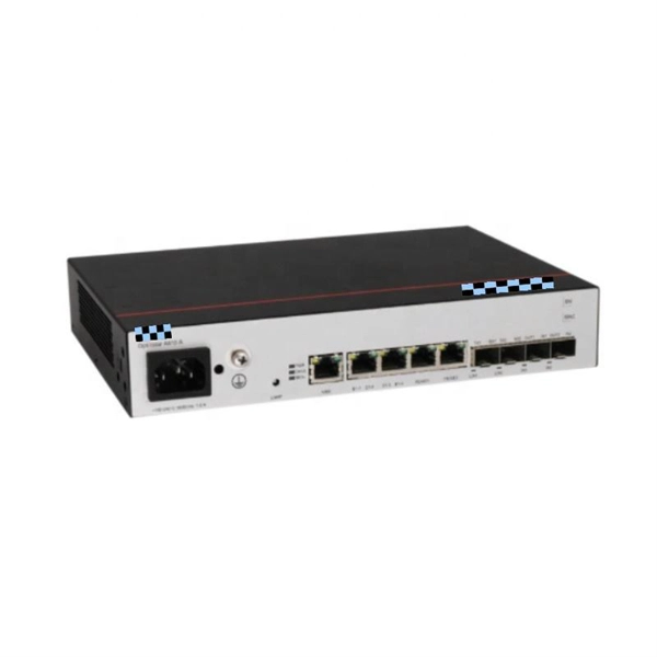
This article examines the key differences among six NADDOD 1. 6T OSFP optical transceivers, focusing on network protocol, thermal structures, transmission reach, and connector types to help network architects make informed deployment decisions for next-generation AI . This article examines the key differences among six NADDOD 1. 6Tbps, the latest Ethernet iteration is poised to further transform data centers to meet our incessant demands for information at our fingertips. While the IEEE, which oversees the Ethernet standard, is expected to finalize the latest iteration of 1. 6TbE standard in 2026, a. ServerBasket provides High Performance Dell PowerEdge AI Servers for Next Generation Computing Environment with High Scalability and Accuracy.
[PDF]

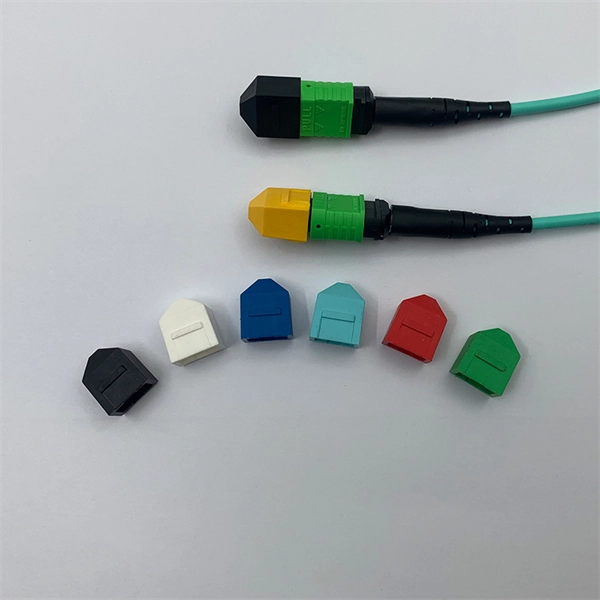
In this beginner-friendly guide, we'll explain what it is, why the “APC” matters, the different types you can buy, how to select the right model, and how to install and test it correctly. What is an SC/APC Fiber Optic Adapter?. Fiber optic adapters, also known as couplers, play a crucial role in fiber optic networks by providing a connection point between two fiber optic connectors. They enable seamless and reliable optical signal transmission between different fiber optic cables, connectors, or devices. Using the wrong type or neglecting cleaning can lead to signal loss and unstable connections. This guide covers adapter types, selection criteria, cleaning tips, FAQs, and B2B customization options to help businesses build reliable and scalable fiber networks. It ensures precise alignment between fibers and facilitates effective transmission of optical signals. Without the proper adapter, signals can degrade or become unstable, which can dramatically decrease the reliability of a network.
[PDF]

Use this guide to learn about the Juniper Networks® 800G optical transceivers and cables, their specifications, and how to install, remove, and maintain these transceivers. Do you have a question about the OSFP-SR8-800G and is the answer not in the manual? Page 1 FS H100 INFINIBAND SOLUTION DELIVERY MANUAL FS 800G&400G T ransceiver Acceptance Testing Guide Copyright © 2024 FS. COM AII Rights Reserved Copyright © 2024 FS. Removing QSFP-DD and QSFP Transceiver Modules 5. Cleaning and Maintenance 6. Handling of Common Problems 9. Overview An optical OSFP transceiver module with MPO-16/APC connector is shown. The OSFP-800G-2xFR4L Optical Transceiver is a high performance, cost effective module for optical data communication applications supporting 800G Ethernet. The OSFP-800G-2xFR4L is designed to operate in switch and router applications supporting OSFP MSA compliant traffic for up to 6km links. This transceiver is a high- performance module for datacenter-range multi-lane interconnection and data transmission. It integrates 8 data lanes.
[PDF]

This comprehensive guide breaks down the internal structure, core components (TOSA, ROSA, lasers), and operational mechanisms of SFP optical modules, enriched with technical insights and real-world applications. Optical Modules (also known as Optical Transceivers) are critical components in fiber optic communication systems. As the core optoelectronic devices operating at the Physical Layer of the OSI model, their primary function is to perform electro-optical and photo-electric conversion during signal. In the era of 5G, AI, and high-speed data centers, optical modules serve as the core bridge for converting electrical signals to optical signals (and vice versa), enabling fast, reliable data transmission across networks. They are used in fiber optic communication systems to transmit data over long distances with minimal loss and interference. This article systematically identifies common anomalies during optical module installation. Combining hardware principles with practical experience, it. When the industry speaks of optical modules, it refers specifically to small, hot-swappable packaged optical modules, which are used on equipment ports and can be hot-swapped during operation, and are mainly used to convert the electrical signals in equipment (usually switches or router equipment).
[PDF]
This article explores the different types of Fiber Optic Sensors, their working principles, and various applications. while constructing a complete Fiber Optic Link (Central Office to Outside Plant to Customer Premise). Hence, this course will. The fiber optic sensor has an optical fiber connected to a light source to allow for detection in tight spaces or where a small profile is beneficial. The optical fiber consists of the core and the cladding, which have different refractive indexes. This is a very interesting and also well-known topic in the research field. Fiber optic sensors play a key role in developing the communication system to sense & measure the change within. Imagine a world where the Internet doesn't just connect but senses —detecting earthquakes, monitoring battery health, or safeguarding critical infrastructure. This is the power of fiber optic sensing, a technology that transforms ordinary optical fibers into the digital world's sensory network. We'll delve into Intrinsic, Extrinsic, and Hybrid fiber optic sensors, explaining how they function. A sensor is a device that measures a physical quantity and converts it into a. Konnexx is an industry leader in Jamaica and the Caribbean, providing world class services in the telecommunication and broadband industries offering a wide range of telecommunication support services for commercial and private entities. We offer comprehensive solution for businesses interested in.
[PDF]

Testing solar panels is easy with a multimeter! To test the current, simply connect the multimeter to the panel's output. Set it to read DC current. A multimeter is an indispensable tool for anyone working with solar panels, allowing for accurate measurements and diagnostics. It empowers users to assess the performance, identify faults, and ensure optimal energy production. Without proper testing and maintenance, solar panels can suffer from. In this article, you will learn the step-by-step process of testing your solar panels using a multimeter. We will cover the essential tools you need, the specific measurements to take, and how to interpret the results. By the end of this guide, you will be equipped with the knowledge to diagnose. With just a simple tool—a multimeter —you can quickly measure your panel's voltage and current. This helps you spot issues early and keep your system running efficiently. Connect the multimeter. 🔋 Learn how to test solar panels using a multimeter — step-by-step! I'll show you how to safely check voltage, amperage, and open-circuit power, so you can confirm if your panels are producing the watts you expect. Perfect for DIY solar builders, RV owners, o. We'll also introduce the Honeytek HK78G 2000V PV Multimeter, a professional tool designed for solar testing. Honeytek, a global.
[PDF]

GOOD WILL INSTRUMENT (SUZHOU) CO. Browse online or download User Manual for Equipment Gw-instek GOS-652G. GW Instek GOS-652G User Manual 50MHz Cursor Readout With Delayed Sweep.. GOS-658G 20MHz Cursor Readout... GOS-652G 35MHz. Caution statements identify conditions or practices that could result in damage to this product or other property. THIS APPLIANCE MUST BE the letter E or by the earth symbol or coloured Green or Green & Yellow. EARTHED The wire which is coloured Blue must be connected to the terminal which is. y have a fraction of the total loss compared to fiber-based equivalents. FBG also provides a latency in the o der of nanoseconds as compared to microseconds in fiber-based solutions. The FBG based DCMs are designed to perfectly mimi the dispersion and dispersion slope characteristic of G. 652 fiber. g sensitivity and low water-peak level. Together they allow unlimited use of the whole telecom wavelength win ow for a great variety of applications.. GOS-653G Basic... GOS-622G. The GOS-653G/652G Series is an example of classic analog oscilloscope design. The GOS-653G /652G cover a broad range of industry applications, such as product design, assembly lines, repair & servicing, and educational purposes for EE laboratories and class experiments. Coupled with various trigger.
[PDF]

Connecting a multi-mode SFP to single-mode fiber creates a major signal mismatch. A small portion of the transmitted light gets captured. This leads to high attenuation and frequent link drops. I suggest you avoid such setups. Use them if essential and with proper mode. A Fiber Channel SFP is a specialized optical transceiver designed exclusively for Fiber Channel (FC) networks, enabling high-speed, low-latency, and lossless data transmission in Storage Area Network (SAN) environments. These transceivers comply with the ANSI INCITS 404-2005 Fiber Channel standard and IEEE 802. 3 for. There are two main types of fiber optic cables: single mode and multimode. Although they can do the same job in some instances, the different construction methods make each of them better suited to certain tasks and budgets. That makes picking between single mode and multimode fiber optic cables an. Single-mode (SMF) and multi-mode fiber (MMF) use different core sizes, sources and wavelengths. Understanding the compatibility constraints prevents costly downtime and troubleshooting. What Is the Difference Between Single Mode and Multimode Fiber? The main difference between these fiber options comes down to how light travels through. What is Single-mode SFP? Before we compare them, we need to know their brief definitions. A single-mode SFP is specially used with the 9/125µm single-mode fiber (SMF) but can not be used with multimode fiber cable.
[PDF]

Get answers to frequently asked questions about broadband services at BTC Bahamas. At Lightcommunication Company, we specialize in comprehensive fiber optic solutions, ensuring superior connectivity through expert services in installation, splicing, and network maintenance. We strive to revolutionize communication by providing cutting-edge fiber optic services that empower. BTC, also known as the Bahamas Telecommunications Company, is the national telecommunications company of the Bahamas. It offers a range of internet services, including fibre optic and DSL connections, and has a wide network of fibre optic cables, allowing it to provide high-speed internet to both. Clear Fiber Technology Solutions is a leading and reputable Telecommunications Contracting and Consulting Firm serving the Bahamas and Caribbean area. We understand the importance of Professional and Reliable Communications Services. We take a comprehensive approach to secure solutions, providing. Our aim is to provide reliable, cost effective, comprehensive solutions with efficient service to assist you in building I. infrastructure you can depend on. We want to be your partner of choice. call on us when you need to build out, upgrade or expand. Along the way we make it our mission to enrich lives and businesses through reliable, fast and future ready technology. Cable Bahamas nurtures education, wellness and cultural growth through dedicated partnerships and.
[PDF]
A well-chosen patch panel not only organises your fibre connections but also provides protection and flexibility for future expansions. In this comprehensive guide, we'll explore the key factors to consider when selecting the perfect patch panel for your network infrastructure. Choosing the right fiber optic patch panel is one of the most important decisions you'll make when building or upgrading a fiber network. While patch. Whether you're planning to upgrade your home internet connection or just curious about how fiber technology works, understanding the essential fiber optic equipment is the first step. From the optical network terminal to the router that brings your home online, each piece plays a critical role in. Structured wiring begins with a structured networking panel. These panels have ports for input cables and output cables. The right structured wiring can deliver top performance from your electronics. The panels accept cable from outside providers to distribute the signals to each room of your home. If you already know what your project requires, check out our complete Fiber Patch Panel selection. What is a Fiber Patch Panel? Fiber optic patch. Fiber optic installation is the way to go! It's super reliable and perfect for streaming, gaming, or using multiple devices. This guide breaks down the process in easy steps so you know what to expect. Aerial Service Drop: A cable coming from a pole to your house, connected at a small box called an.
[PDF]
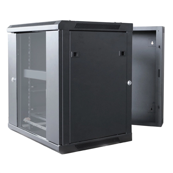
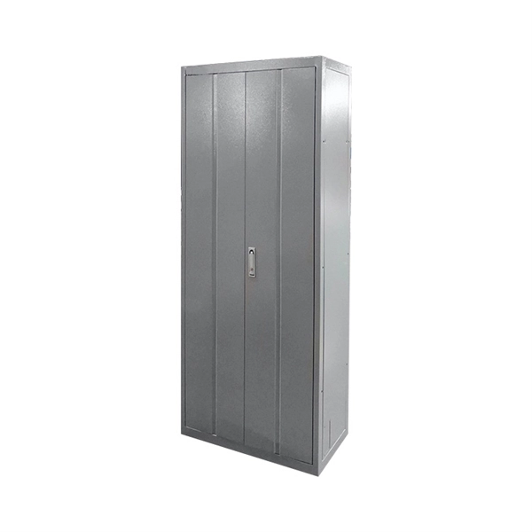
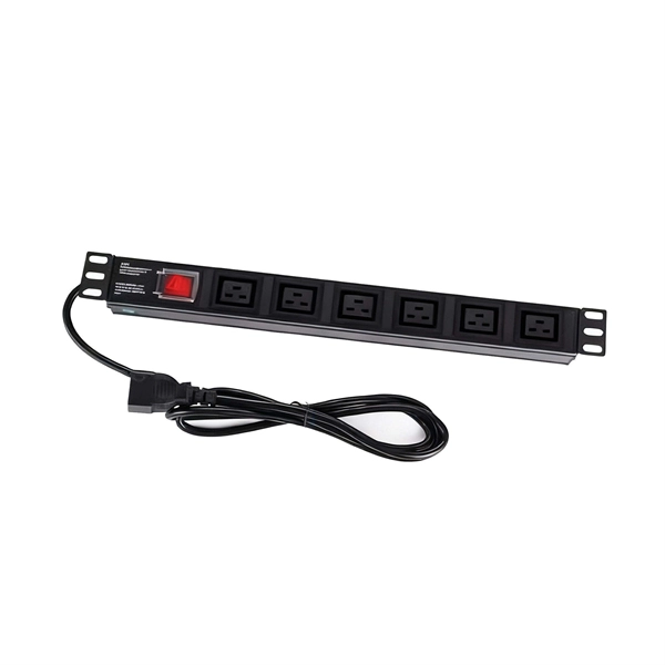
In this guide, we'll explore top network rack options like the TECMOJO 12U Open Frame Network Rack and the ECHOGEAR 10U Network Rack. We will also cover features to consider, such as size, mounting style, and additional accessories. A network rack is essential for organizing and securing your IT and AV equipment. Whether you need a wall-mounted or floor-standing rack, the right choice can make a big difference in your setup. The rankings reflect our opinion and should be a good starting point for shopping. By purchasing the products. These racks provide a secure and organized way to house your valuable equipment, ensuring optimal performance and longevity. Choosing the right rack for your home setup depends on several factors, including the size of your equipment, the available space, and your budget. In this article, we'll. Organize your tech with our top-rated network server racks for small home offices. Find the perfect space-saving solution for your gear and shop our guide today. An unmanaged tangle of Ethernet cables and overheating networking equipment is a disaster waiting to happen in any home office. Investing. Ground-Mounted Load Capacity, with Locking Glass Door Side Panels, for IT Equipment, A/V Devices Need help? Organize your IT and AV equipment with sturdy network racks. Explore our top picks today. In the bustling realm of technology, network racks serve as the unsung heroes of organization and efficiency. Whether you're a seasoned IT.
[PDF]

This helps keep fiber optic cables safe from harm and signal problems when you put them in. Use the right lubricant. Follow the rules for tension and bend radius. Try new methods like air blowing. Use smart. Fiber optic cable is surprisingly strong, durable and pliable; however, several best practices should be followed to ensure a successful cable installation. This article explores recommendations for pulling and installing fiber optic cable. This makes sure the cable pull is smooth and safe. Use smart monitoring devices. The Future Ready Solutions Tools & Test. A duct is available from point A to point B, a pull tape is blown in, a fiber optic cable is attached to it and the cable is pulled through the duct. Sounds simple, doesn't it. Recent observations and conversations with more than a few people in the fiber optic business have indicated. Route plan to ensure the duct run maintains the minimum bend diameter of the cable. For more information and all recommendations for installation, refer to Corning Optical Communications Standard Recommended Procedure SRP 005-011, "Duct Installation of Fiber Optic Cable". more Route plan to ensure.
[PDF]