In this tutorial, we will show you how to fusion splice two fiber optic strands together in an easy 12 step process. The answer lies in splicing, both fusion and mechanical. Whether you're a professional technician or a DIY enthusiast, understanding the process of fusion splicing fiber optic cables is essential for maintaining high-speed communication networks. - Fiber Instrument Sales What is Fusion Splicing? How fiber optic splicers work, types, what they are used for. Steps to use this equipment and including how to test your fiber splice. The guide covers everything from basic principles of fusion splicing to detailed procedures; it is intended to provide both newbies and professionals with the necessary knowledge and skills. The operation and skills of fiber optic fusion splicing technology can be mainly divided into five steps: fiber stripping, fiber cutting, fiber melting, fiber sleeve, and fiber winding. And tools used for fiber fusion: fusion splicer; fiber cleaver; cable stripper; fiber optic stripper; alcohol;.
[PDF]
A beam splitter or beamsplitter is an that splits a beam of into a transmitted and a reflected beam. It is a crucial part of many optical experimental and measurement systems, such as, also finding widespread application in.
[PDF]
The answer is yes, and it's a practice widely used in the industry to distribute signals to multiple destinations without degrading the signal quality significantly. This article delves into the methods, benefits, challenges, and practical applications of splitting fiber lines. A fiber optic splitter is a passive optical component that divides a single incoming optical signal into two or more outgoing signals, or combines multiple incoming signals into one. Its primary role is in Passive Optical Networks (PON), which are the foundation of. Fiber splitters are critical in optical networking, skillfully dividing a single light signal into multiple outputs for diverse applications. Their passive operation allows for widespread use in telecommunications, data distribution, and sensor systems, making them a backbone technology in. Power splitters (also commonly called “optical splitters”) are devices that divide an optical signal into multiple, equal-intensity output signals. The split ratios are usually even, like 1:2, 1:4, 1:8, and up to 1:32. Other split ratios are available, but usually come at a higher cost as they have. An optical splitter is a passive bidirectional element, which is used to connect a large number of subscribers/ONUs to an OLT. It is one of the most important elements of all FTTx PON and OLAN networks. What is Fiber Line.
[PDF]
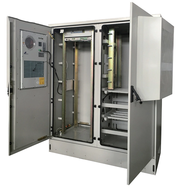
The securing, storing and supporting of fiber optics and splices makes up an important step of fiber optic deployments in the field. Whether connecting to aerial or underground cables, telecommunication.
[PDF]

The BA-1 device produces step attenuation of a laser beam to a maximum of about 44 dB . With the preattenuator beam splitter, denoted by SI, this range can be extended as much as another 3 0 dB. The various low level beams generated by BA-1 can be used for detector respon-sivity and. Danielson, B. (1977), Measurement procedures for the optical beam splitter attenuation device BA-1:,, National Institute of Standards and Technology, Gaithersburg, MD, , https://doi. 77-858 (Accessed February 10, 2025) If you have any questions about this publication or. Beam splitters are optical devices that play a crucial role in various scientific and industrial applications. They are used to divide a beam of light into two or more separate beams. NBS interagency report is a publication of the U. The papers are in the public domain and are not subject to copyright in the United States. The BA-1 system is designed for use at. The attenuation ratios of these wavelengths are calculated values. An analysis of the estimated uncertainties is. SPLITTER ATTENUATION DEVICE BA-1 B. Danielson Measurer::ent procedures are described for the step attenuation of laser bearriS up to 44 dB using a specially constructed attenua- tor box (BA-1). a laser beam) into two (or sometimes more) beams, which may or may not have the same optical power (radiant flux).
[PDF]
In this work, we extend these fundamental properties to measures of similarity between states, provide inequalities for creation and annihilation operators beyond the Cauchy-Schwarz inequality, prove a conjecture [Hertz et al., PRA 110, 012408 (2024)] dictating that nonclassicality. A beamsplitter is a common optical component that partially transmits and partially reflects an incident light beam, usually in unequal proportions. In addition to the task of dividing light, beamsplitters can be employed to recombine two separate light beams or images into a single path. This. Beamsplitters separate incident light into two or more beams of the same wavelength. These exiting beams are differentiated by either their optical power (non-polarizing) or polarization states (polarizing). It is a crucial part of many optical experimental and measurement systems, such as interferometers, also finding widespread application in fibre optic telecommunications. Conversely, it can also combine multiple signals into one. Its primary role is in Passive Optical Networks (PON), which are the foundation of. Our recent proof for the entanglement properties of states interfering with the vacuum on a beam splitter led to monotonicity and convexity properties for quantum states undergoing photon loss [Lupu-Gladstein et al. 03423 (2024)] by breathing life into a decades-old conjecture.
[PDF]
An Ethernet splitter consists of two RJ45 jacks, one on each side. These jacks are used to connect the Ethernet cable to the splitter. Depending on the type of splitter you have, there may also be other ports or connectors that need to be connected as well. A wiring diagram for an Ethernet splitter can make the installation process a breeze. It does not increase speed or create extra bandwidth. It simply divides signal pairs. This tool works best in basic setups where running another cable is not possible. An Ethernet splitter. An Ethernet Splitter works by separating a single line into two or more outgoing lines, allowing multiple users to draw from the same source without affecting bandwidth. You may also want to know: Are Bing and Yahoo the Same? · Are Sony and Murata Partners? The term “Ethernet splitter” is often. Repeat step 2 to connect a second Network Device to the Cable Adapter. To view manuals, FAQs, videos, drivers, downloads, technical drawings, and more, visit www. to an existing Network. Scenario: A company has two offices (A and B). A single CAT5 Ethernet drop.
[PDF]
A fiber-optic splitter, also known as a, is based on a of an integrated waveguide power distribution device, similar to a The system uses an optical signal coupled to the branch distribution. The splitter is one of the most important in the link. It is an optical fiber tandem device with many input and output terminals, especially applicable to a passive optical network (,,,.
[PDF]

Non-polarizing beamsplitters are specified by their splitting ratio, i. the ratio of P-polarized light to. A beam splitter or beamsplitter is an optical device that splits a beam of light into a transmitted and a reflected beam. It is a crucial part of many optical experimental and measurement systems, such as interferometers, also finding widespread application in fibre optic telecommunications. a laser beam) into two (or sometimes more) beams, which may or may not have the same optical power (radiant flux). Different types of beam splitters exist, as described in the. The collimated incident laser beam passes through the beam splitter, and the output beam is emitted at a specific separation angle on the output beam array. The following figure is an introduction to the basic settings of a beam splitter. Circular beamsplitters, plate beamsplitters and cube beamsplitters can be purchased for polarizing or non polarizing beamsplitting. Beamsplitters are optical components used to split incident light at a designated ratio into two separate beams.
[PDF]
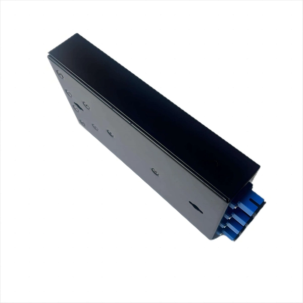
The Splitter Fiber Optic 32 Way is designed for high-performance signal splitting in fiber optic systems. With low insertion loss, it ensures minimal signal degradation, providing excellent uniformity and broadband operation. Excellent quality is the foundation of FiberMall' s survival and development. Our operation team are experts with many years' experiences in optical communication industry. Many of them have the qualification of OEM for first-class. Accurate Optical Performance - This 1x8 optical splitter maintains 10. Industrial-Grade Construction - Robust electronic components and accurate grinding process create. Low Insertion Loss 2. 00mm Cassette PLC Splitter 1X16 For FTTX PON Planar lightwave circuit (PLC) splitter is a type of optical power management device that is fabricated using silica optical waveguide technology to distribute optical signals from Central Office (CO) to multiple premise locations. This item is a recurring or deferred purchase. Low Polarization Dependent Loss. Excellent Environmental Stability. Telcordia GR-1221 and GR-1209. Fiber to The Point (FTTX). Passive Optical Networks (PON). Local Area Networks. (6+1)×1/ (18+1)×1 fiber pump signal combiner features high pump efficiency, low insert loss, cost-effective, stable and reliable. This combiner can be integrated into medium and high power fiber laser, fiber. Miniaturized 1*N adjustable fiber optic splitting module is the core module in optical.
[PDF]

Fiber splitters serve as essential components in optical networks. These devices divide an optical signal from a single input into multiple outputs. This process enables efficient signal distribution across various network points. Fiber splitters function without the need for external. In the intricate web of modern fiber optic networks, where data travels at the speed of light across continents, fiber optic splitters play a silent yet pivotal role. These unassuming devices enable a single optical signal to be divided into multiple paths, making them indispensable for sharing. A fiber splitter, also known as a beam splitter, is a passive optical device that splits an optical signal into multiple signals. By dividing a single optical signal into multiple signals, fiber. Fiber optic splitters are vital in modern communication networks. Fiber optic splitters, such as plcsplitter and fbt splitters, are crucial in maintaining signal integrity, with considerations for IL (Insertion Loss) and RL (Return Loss). They are integral components in the world of telecommunication and data networking, crucial to maintaining reliable and efficient communication infrastructures. There are two primary.
[PDF]
Beam splitters are classified by construction (plate, cube, pellicle, polka dot) and by function (standard, non-polarizing, polarizing, dichroic). Construction determines ghosting, damage threshold, and form factor. Function determines how polarization and wavelength are. Beamsplitters are optical components used to split incident light at a designated ratio into two separate beams. Additionally, beamsplitters can be used in reverse to combine two different beams into a single one. Beamsplitters are often classified according to their construction: cube or plate. A beam splitter (or beamsplitter, power splitter) is an optical device which can split an incident light beam (e. a laser beam) into two (or sometimes more) beams, which may or may not have the same optical power (radiant flux). It is a crucial part of many optical experimental and measurement systems, such as interferometers, also finding widespread application in fibre optic telecommunications. It is also possible to combine the separated beams. Types of Beam Splitters 2. They are found in different configurations and can be used in multiple applications. However, how they work exactly often remains overlooked. These versatile tools can split both laser and regular light, depending on the application in question.
[PDF]

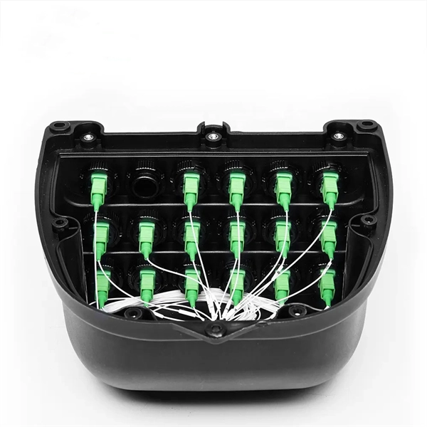
Not all splitters are created equal. Here are the main types you'll encounter: The "1×N" notation indicates one input fiber and N output fibers. A 1×2 splitter divides the signal into two outputs, while a 1×8 splitter divides it into eight. The more splits, the. By dividing a single optical signal from a central Optical Line Terminal (OLT) into multiple outputs for Optical Network Terminals (ONTs) at users' homes, splitters eliminate the need for dedicated fibers to each residence—slashing infrastructure costs while scaling network reach. This guide. A fiber-optic splitter, also known as a beam splitter, is based on a quartz substrate of an integrated waveguide optical power distribution device, similar to a coaxial cable transmission system. The optical network system uses an optical signal coupled to the branch distribution. The fiber optic. Optical couplers can split or join signals in fibers. You can connect many users to one port with 1:n or 2:n splitters. These devices work both ways, which helps strong network communication. In a Passive Optical Network (PON), a single optical fiber carries massive amounts of data using light. They are named by the number of inputs and outputs, so a splitter with one input and 2 outputs is a 1X2, and a PON splitter with one input and 32 outputs is a 1X32.
[PDF]
For stubborn residues, xylene, acetone, or 70% ethanol in distilled water can be used, with xylene being the most effective but potentially damaging to optical components. It is crucial to avoid rubbing dry cloths on dry glass surfaces and to wear latex gloves to prevent. I guess there are two ways to look at this ; the oil will cause dirt and such to stick to bar but might help on wear and dry nothing sticks. What's everyone's thought on this and what do you do ? mat60, amateur cutter, Slocum and 9 others like this. The fresh grease forces out. Should I grease the splitter beam or leave it clean? I guess the grease will attract dust and sand, causing grinding paste and potentially more wear and tear. My splitter came with grease nipples on the beam, so I often added some grease. I am just not convinced this is a good idea. Any advice?. This discussion focuses on the proper cleaning techniques for polarizing beamsplitter cubes, emphasizing the importance of using appropriate materials and methods to avoid damaging coatings. The recommended cleaning solution is "Sparkle" brand glass cleaner (purple variant), applied with Q-tips or.
[PDF]
A beam splitter or beamsplitter is an optical device that splits a beam of light into a transmitted and a reflected beam. It is a crucial part of many optical experimental and measurement systems, such as interferometers, also finding widespread application in fibre optic telecommunications. DesignsIn its most common form, a cube, a beam splitter is made from two triangular glass which are glued together at their base using polyester,, or urethane-based adhesives. (Before these synthetic,. Beam splitters are sometimes used to recombine beams of light, as in a. In this case there are two incoming beams, and potentially two outgoing beams. But the amplitudes. For beam splitters with two incoming beams, using a classical, lossless beam splitter with Ea and Eb each incident at one of the inputs, the two output fields Ec and Ed are linearly related to the inputs thro.
[PDF]