
Follow a step-by-step process: mark the location, drill holes, insert anchors, and secure the box for a weatherproof fit. Apply weatherproof sealant around the box edges and cable entry points to prevent water ingress. Installing an electrical box on an exterior wall can seem daunting, but with the right guidance, it can be a straightforward task. Whether you are adding an outdoor outlet for convenience or setting up lighting, understanding the process is key. This guide will walk you through the essentials of. An electrical junction box is a protective housing designed to enclose and shield electrical wire connections or splices. For outdoor installations, the box must defend these sensitive splices against moisture, dust, temperature fluctuations, and physical impacts. Safety remains crucial during installation. It takes the incoming power and safely distributes it to different circuits throughout your building. Whether in a home or an industrial facility, this box keeps your electrical setup organized, functional, and efficient. Whether adding a GFCI outlet for safety or upgrading an exterior outlet for weather-resistant durability, it's essential to follow proper electrical wiring. In this video, I'll show you how to install a weatherproof outdoor electrical box — safe, secure, and code-compliant.
[PDF]
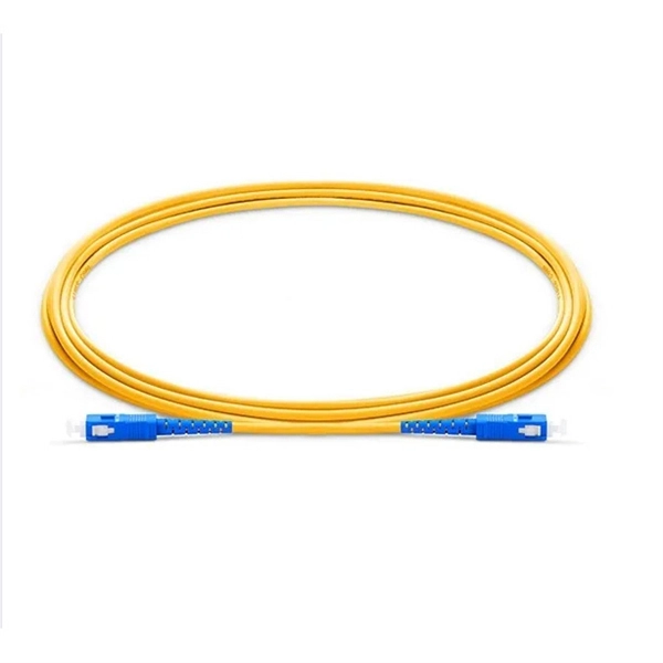
An electrical pigtail is a short piece of wire used to connect an electrical device, such as a switch or receptacle, to the main circuit conductors within a junction box. It acts as a jumper between the device terminal and the spliced bundle of circuit wires. This technique ensures the device is. Are a pigtail and a jumper wire the same thing, how are they different ? A jumper connects two devices or terminals together. Like you can jumper the top and bottom halves of a duplex receptacle if the bridge gets broken off. You can. The most intuitive difference between the two is that only one end of the pigtail has a connector, and both ends of the jumper have a connector. Optical Fiber Jumper: also known as optical fiber connector, both ends have connectors. Similar to coaxial cable, but without mesh shielding, for jumper. This detailed guide will take you through the basics of jumper wires, their types, applications, and the step-by-step process of connecting them securely and effectively. What Are Jumper Wires? Jumper wires are insulated wires used to connect two points in a circuit. They usually come with. Pigtails play a crucial role in ensuring safe and efficient connections within electrical systems, especially when dealing with multiple wires or limited space. Understanding what a pigtail is and how it works can make your wiring projects smoother and safer.
[PDF]
These two categories define how light travels through the fiber core: Transmits a single light mode; very low attenuation; supports long-distance transmission up to 100 km or more. Transmits multiple light modes; higher dispersion; best for shorter distances. The most common distinction is between single mode vs multi mode fiber optic cable. There are many classifications of optical cables, due to the installation environment. It has stronger pressure resistance, corrosion resistance, greater tensile. In the landscape of network infrastructure, three primary cable categories dominate connectivity: twisted-pair copper cables, coaxial cables, and fiber optic cables. While copper-based solutions (such as Cat5e/Cat6 for twisted pair or RG-6 for coaxial) have long served as workhorses for local and. We'll cover single mode, multimode, and armored fiber cables below. Single mode fiber optic cable is made up of a small diameter glass or plastic core surrounded by cladding, which is a layer of reflective material. This small diameter core, typically around 9 microns in diameter, allows only one. There are two main types of fiber optic cables: single mode and multimode. Although they can do the same job in some instances, the different construction methods make each of them better suited to certain tasks and budgets.
[PDF]
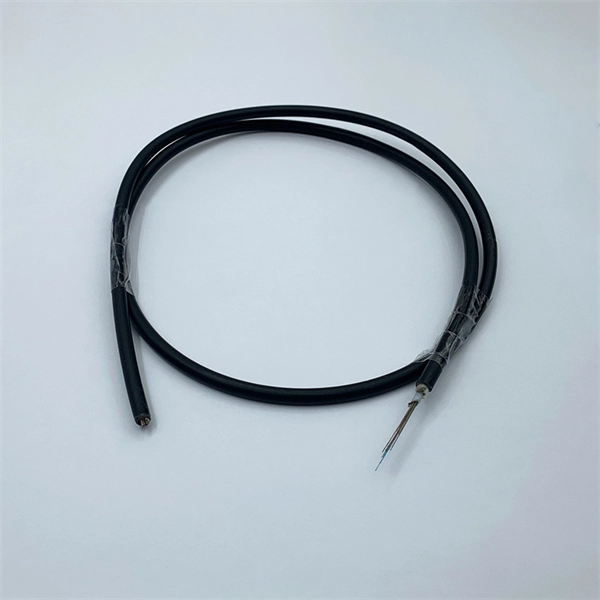
Double jacket fiber optic cable is usually the right choice when a route faces outdoor exposure, building-entry transition, direct-burial risk, rodent pressure, or higher mechanical abuse than a standard indoor cable can handle comfortably. Outdoor fiber optic cable plays a critical role in connecting buildings, deploying security and access control electronics, extending networks across campuses, supporting broadband deployments and enabling reliable communication in harsh environments. The key is that “double jacket” is not a universal premium. Fiber optic cables are the backbone of modern communication systems, offering exceptional speed, bandwidth, and resistance to electromagnetic interference. Designed to survive decades of UV exposure, temperature swings, moisture, mechanical stress, and rodent attacks, these. Fiber optic cables are specialized cables that use light to transmit data at incredibly high speeds. Unlike traditional copper cables, fiber optics is immune to electromagnetic interference, offers higher bandwidth, and allows for more reliable, long-distance connections. These cables are widely. Plan your outdoor fiber installation carefully by surveying the site, choosing the right cable type, and following FOA and OSP standards to ensure reliability. Select the best installation method—direct burial, aerial, conduit, or underwater—based on your environment and future network needs.
[PDF]
The normal recommendation for fiber optic cable is the minimum bend radius under tension during pulling is 20 times the diameter of the cable (d). This includes pulling tension, minimum bend radius or diameter and crush loads. Installers must understand these specifications and know how to install cables without. Fiber optic cable bend radius is a critical mechanical parameter that determines how sharply a cable can be bent without risking microbending, macrobending, signal loss, or long-term structural fatigue. Proper bend radius control ensures the integrity of optical performance and protects the glass. Fiber optic cables have revolutionized communication networks, providing extremely fast data transmission through pulses of light traveling along thin glass fibers. However, these slim cables often need to twist and turn during infrastructure builds and maintenance. So an important question arises:. Ignoring the minimum bend radius for fiber optic cable can result in signal loss, increased attenuation, and long-term reliability issues. Have a network installation project? What's The Bend Radius of Fiber Optic Cables? The bend radius of fiber cables. Always keep the fiber optic cable bend radius at least 20 times the cable diameter during installation and 10 times after installation to prevent damage and signal loss. Use bend-insensitive fiber optic cables in tight spaces to reduce signal loss and allow sharper bends, but still follow.
[PDF]
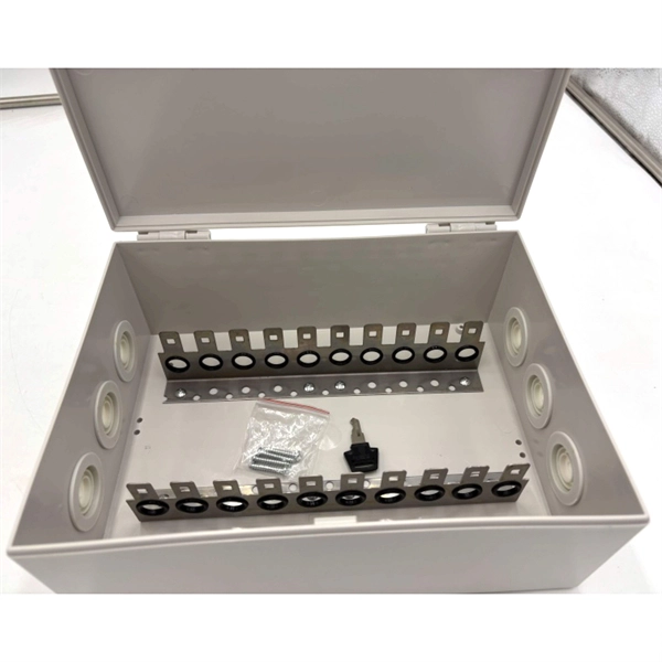
Start by examining the plastic cover closely to identify any tabs or locking mechanisms that may be holding it in place. This robust enclosure houses either the main service disconnect or a sub-panel, acting as a control point for electricity distribution to the property or a dedicated outdoor system like a pool or workshop. Gaining access to the panel's interior is usually necessary for simple tasks like resetting a. Opening electrical boxes outside can be a tricky endeavor. Without the proper tools, knowledge, and safety measures, it can also be dangerous. However, with a few simple steps, you can open an outdoor electrical box safely and efficiently. This is how you can open them to have access to the plug-ins. Once you've loosened the. This guide will explore the steps and considerations for safely and effectively punching out a plastic electrical box. Ensure the wires are not powered before starting work. Flat-head screwdriver, electrical pliers, hammer, and a suitable meter or tester. Locate. Before you attempt to open an outdoor breaker box, it's crucial to prioritize your safety. Here is a set of guidelines to ensure you undertake this task without any hazards: Confirm power is disconnected to the unit by turning off the main breaker or disconnecting the main fuse.
[PDF]
Looking for reliable outdoor power solutions in Casablanca? This guide explores top local suppliers, key features to consider, and emerging trends in Morocco's renewable energy sector. Morocco's ambitious renewable energy targets and growing tourism sector make it a hotspot for outdoor power solutions. With 52% of electricity slated to come from renewables by 2030, businesses and adventurers alike need reliable off-grid systems. Whether you're a homeowner, business operator, or outdoor enthusiast, discover how to find the right power supply. Discover Morocco's top solar energy system suppliers, each pioneering a sustainable future with unique, innovative solar solutions. Morocco, with its abundant sunshine, has embraced solar energy as a cornerstone of its renewable energy strategy. As the demand for sustainable and cost-effective. Solar Power Solutions Pvt Ltd is the premier solar company in Morocco. Our comprehensive range of services includes solar installation, solar energy solutions, and. While DIY kits exist, professional services ensure compliance with Morocco's ONEE regulations and proper weatherproofing. One client learned this the hard way—their ungrounded system failed within 6 months during heavy rains. Specializing in renewable energy integration, we've deployed over 120. Discover vast solar energy projects powering Morocco, including large-scale solar farms designed to harness the desert sun efficiently. Transforming water into energy.
[PDF]

Fiber optic loss calculation formula: Total link loss (LL) = Cable attenuation + Connector attenuation + Fusion attenuation [Note: If there are other components (such as attenuators), their attenuation values can be added]. Intrinsic Optical Fiber Losses comprise of absorption loss, dispersion loss and scattering loss caused by the structural defects. The detailed information about these optical losses and how to reduce them are. Calculate fiber optic signal loss based on cable length, attenuation, and connector losses. Determine cable loss, connector loss, and total system loss in decibels (dB) to assess signal quality and repeater requirements. Fiber optic loss is calculated in two parts: cable loss and connector loss. This calculator determines fiber loss based on input power, output power, and the length of the fiber optic cable. In summary, fiber optic loss is. Use this worksheet to input values for all variables that will impact your system's performance. After entering your values, please ensure you click the 'Calculate Link Loss' button at the bottom of the page to generate your total link loss. This step is necessary to see if your system falls within. Optical fiber loss is a term for signal loss affecting transmission reliability. Optical fiber loss is.
[PDF]
We deliver custom-made cable trays to meet the needs of your project, ensuring easy installation and reliable support for your cables. The nVent CADDY Wire Basket Tray System is an industry leading continuous pathway support solution for today's high-performance cabling systems. This robust. See our products in a new more user-friendly way We have wire trays, data racks and all accessories you need to install your cables in an easy, fast and high qualitative way. Nordic Wire Tray becomes Nordic Wire Tray. New name, new look, same Nordic quality We continue to drive innovation in cable. How can we improve? Choose from our selection of wire trays, including over 850 products in a wide range of styles and sizes. Same and Next Day Delivery. ShowMeCables stocks a range of cable management, low voltage wire holders including Duct, Spools, D-Rings, Grommets, Lacing Bars and Strips, Neat-Patch, Wall-Mounted, Vertical, Horizontal, Cable Tray and Cable Tray Accessories. Brands include ShowMeCables, L-com, ICC, Middle Atlantic, Panduit, Hosa. Count on Monosystems to deliver products, solutions and expertise that are tailor-made for the market you serve. For over 50 years, we have dedicated ourselves to providing Industry with best in class wire management solutions and to helping solve mission critical issues. Discover the benefits of each system to make an informed decision tailored to your specific application. We also offer a wide range of accessories in all.
[PDF]
Get the wrong connector type, the wrong polish, or skip proper fusion splicing technique—and you're looking at elevated signal loss, increased back reflection, and a field termination that fails certification. Thoracostomy tubes are indicated for management of air or fluid in the pleural cavity. Pigtail catheters have emerged as an effective and less morbid alternative to traditional large bore chest tubes for evacuation of pleural air or fluid. However, they do not come without complications which. Traditionally large-bore tube thoracostomy has been the standard of care for treating many acute intrathoracic pathologies. However, the advent of less invasive small-bore chest tubes, also known as pigtail catheters, has gradually led to a paradigm shift. They are used to treat a variety of conditions including pneumothorax, pleural effusion, and postoperative evacuation of air and fluid. There are a number of types and sizes of chest tubes available ranging. Return loss is the ratio of signal power injected from a source compared to the amount that is returned or reflected back toward the source. It is a critical performance parameter in both copper twisted pair and fiber optic cabling systems, because it can interfere with the transmitted signal and. Executive Summary: A fiber optic pigtail is one of the most commonly specified yet least understood components in structured cabling.
[PDF]
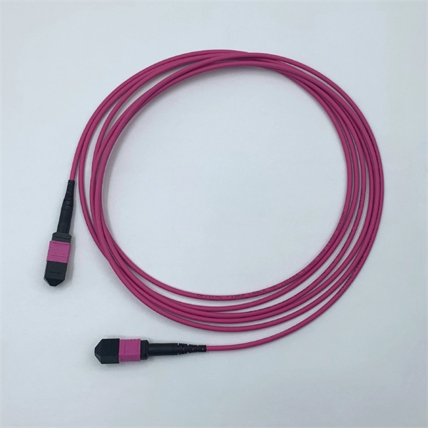
Mixing singlemode and multimode pigtails in the same link is a common and costly mistake. The core diameters (9 µm vs. 5 µm) are fundamentally incompatible—attempting to splice or connect them results in massive insertion loss (often 10+ dB) that will fail every optical power. Fiber optic pigtails play a critical role in modern optical networks, serving as the interface between optical fibers and active or passive devices through fusion splicing. Among the various options available, singlemode fiber pigtails and multimode fiber pigtails are the two most widely used. Choosing between single-mode and multimode fiber optic pigtails is one of the most important decisions in network design. These differences determine which transceivers work with which fiber and how far signals can travel. Understanding the compatibility constraints prevents costly downtime and troubleshooting. Choosing the right pigtail directly impacts signal transmission distance. So what's the cause of mix-using multimode and single-mode fiber? As we see, the optics applied in point-to-point interconnection are symmetrical. For instance, end A with a 10G SFP+ port houses a 10GBASE-SR SFP+ module.
[PDF]

Optical return loss is the amount of light that is reflected back to the source, this reflected light is measured at each connector and splice at each point over the entire fiber link. This is always measured in dB (decibels) and will be displayed as a negative number. The closer the number is to. The polish of a singlemode fiber endface plays a significant role in reflectance. Understand what you need before you specify. The Institute of Electrical and Building the ORL story Electronics Engineers (IEEE) recently Within a fiber-optic channel or path-released new specifications within way. Optical Return Loss (ORL) in fiber optics refers to the amount of light that is reflected back toward the source in a fiber link. ORL is usually expressed in decibels (dB) as a positive value, with. Return loss (RL) is also called reflection loss. When high-speed signals enter or exit a part of an optical fiber, such as an optical fiber connector, discontinuity and impedance mismatch may cause reflection, which is the return loss of an optical fiber. Poor ORL is commonly caused by dirty connectors, poor splices, mismatched connector types, or damaged fibers. ORL is measured using ORL meters. Home Coherent Optics Optical Return Loss (ORL) Explained Comprehensive Guide to Understanding and Managing Back-Reflections in Fiber Optic Systems What is Optical Return Loss (ORL)? Optical Return Loss (ORL) is a critical parameter in fiber optic systems that quantifies the amount of light.
[PDF]

The typical specification range of return loss of a fiber connector is -15 dB to -60 dB. Return loss is also known as reflection loss. It indicates the amount of signal reflected back to the transmitting end. Return loss refers to the power loss caused by the reflection of part of the signal back to the signal source during transmission due to the discontinuity of the transmission. Insertion loss, also known as attenuation, is the loss of optical power that occurs when light passes through a fiber optic connector. It is caused by factors such as misalignment, air gaps, and imperfections in the connector components. The lower the insertion loss, the better the performance of. Reflectance (which has also been called "back reflection" or optical return loss) of a connection is the amount of light that is reflected back up the fiber toward the source by light reflections off the interface of the polished end surface of the mated connectors and air. It is also called. Insertion Loss (IL) is the amount of optical power lost as the signal travels from one point to another in a fiber optic link, usually across connectors or splices. Formula for. In optical fiber communication, insertion loss and return loss are two important parameters to evaluate the quality of interfaces between some optical fiber components, such as optical fiber connector, fiber patch cable, pigtail fiber, etc. While it's natural to have.
[PDF]

Select the correct wavelength and set your reference. You measure optical power in dBm or insertion loss in dB. Consistent procedures ensure accuracy. Measure total signal loss from fiber, connectors, or splices. Optical fiber attenuation is the attenuation per unit length of optical fiber, and the unit is dB/km. When connecting two optical fibers, there will be loss inside any connector or joint. Consistent measurement techniques. While optical power meters are the primary power measurement instrument, optical loss test sets (OLTSs) and optical time domain reflectometers (OTDRs) also measure power in testing loss. TIA standard test FOTP-95 covers the measurement of optical power. Optical power is based on the heating power. Light Source: The CMA5 Series Light Sources provide an economical and stable laser source for use in point-to-point attenuation measurement. They feature a rugged design, built to withstand the difficult testing environment of fiber optic cable installation and maintenance. The CMA5 Light Sources. When talking about optical measurements, wavelength basically means how far a wave pattern repeats itself, usually measured in nanometers (nm). Commonly, a power meter on its own is used to measure absolute.
[PDF]

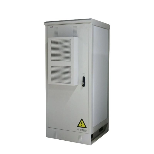
An MV switchgear cabinet assembly line is a production system designed to streamline the manufacturing process of switchgear cabinets. Each step of the process requires precise control and strict execution to ensure the quality and performance of the final product. Core Function Module Our switchgear production. Switchgear cabinets are divided into high-voltage cabinets and low-voltage cabinets. The. Features: 4. 3 RGV adopts frequency control to make sure of the stable transimission. 4 Assembly line uses module design with flexible deployment. Company's head office, Suzhou Kiande Electric Co., is located in Suzhou. Manufacturing center, Kiande (Zhenjiang) Automation. A complete sets of switch gear production line refers to a modern manufacturing system specifically designed for mass-producing complete sets of switch gear. Complete sets of switch gear production line integrates processes, equipment, personnel, and management systematically to achieve efficient. Kiande, a trusted manufacturer and supplier, is offering wholesale switchgear production lines straight from China. Our production lines are built with the latest technology and adhere to strict quality standards, ensuring efficient and reliable performance. Suitable for power systems, industry and new energy fields, helping upgrade global power.
[PDF]