Fiber optic cable can be run anywhere from 300 meters up to 80 kilometers (roughly 50 miles) depending on the cable type, transceiver used, and network standard. For most enterprise or data center applications using multimode fiber, the practical limit sits between 300 m and 550 m. Fiber optic cable transmission distance is determined by two primary physical factors that affect signal quality as light travels through the fiber medium. The greater the distance, the greater. Many factors decide the fiber cable distance, but the key factors include the below six aspects. Attenuation First is the attenuation of the optical fiber. OM2 extends this to 82 meters. OM1 fiber and OM2 fiber don't support these higher speeds. OM5 fiber matches OM4 at. For instance, without amplifiers, single-mode fiber can reach 50-60 miles and can support data rates of 1 Gbps or 10 Gbps. With amplifiers, such as Erbium-doped fiber amplifiers (EDFAs), the distance can be extended to 600 miles or more, and even further with additional amplifiers for long-haul.
[PDF]
Buyers typically pay for fiber laying by combining material costs, labor time, and permitting plus trenching or aerial support fees. The main cost drivers are trench depth, fiber count and type (single-mode vs multi-mode), conduit requirements, and local permitting rules. This guide walks through each stage of underground fiber installation—from route planning and conduit selection to splicing, termination, and testing—to help ensure long-term network performance and reliability. A successful underground fiber optic cable installation begins with careful planning. Installing underground fiber optic cables is critical to establishing high speed internet infrastructure that delivers reliable connectivity for businesses nationwide. Unlike traditional copper systems, fiber optic cables require specialized handling techniques and precise installation methods to. Underground cables are pulled in conduit that is buried underground, usually 1-1. 2 meters (3-4 feet) deep to reduce the likelihood of accidentally being dug up. From the initial site survey to the final fiber to the home (FTTH) connection, every stage requires careful planning, coordination, and. This comprehensive guide walks through the essential steps and best practices for successful underground fiber optic cable deployment, ensuring optimal performance and longevity of your network installation. This article provides cost.
[PDF]
Power over Ethernet (PoE) does not work directly over fiber-optic cables because fiber-optic cables are designed to transmit data using light, and they do not conduct electricity. PoE requires copper cables (such as Cat5e, Cat6, or Cat6a) to deliver both power and data. Power over Ethernet (PoE) is a useful technology in powering remote devices, but as we see with any copper network cable, the challenge lies in the limited distances of UTP cabling. The maximum distance for Power over Ethernet (or any network data transmission) is 100 meters or 328 feet. However, selecting the right PoE switch requires careful consideration of factors such as projected organizational growth and device. In the field of network cabling and device power supply, Power over Ethernet (PoE) technology has become widely adopted due to its ability to transmit both data and power over a single Ethernet cable. In industrial environments, industrial switches are key network devices that are adapted to harsh. IP cameras that are part of a modern surveillance system are deployed using PoE technology that involves the use of copper based network cabling like CAT5e or CAT6 that has a data transmission limit of 100m (328ft). While that is adequate for installations for a home or small business, large scale. They have dual-port choices and are easy to set up. Media converters work well in many places. You do not have to worry about distance.
[PDF]
Actelis' fiber portfolio includes our managed layer 2 fiber switches and aggregation devices designed to extend connectivity over fiber, as well as our hybrid fiber-copper ethernet access devices that.
[PDF]
The layer 2 switches prevent over-crowding of data packets in transmission links and access devices. · Layer Positioning: The data link layer (Layer 2) of the OSI model, realizing local forwarding of data frames based on MAC addresses. · Core Task: Establishing direct interconnections between devices within a local area network to ensure efficient communication within the same network segment. ·. The core layer is the backbone of the network. It provides a high-speed connection between different distribution layer devices. The distribution layer connects the access layer to the core layer. When designing a campus LAN, you may. In enterprise networking, the hierarchical three-tier model is divided into three distinct roles: access switches (which connect end-user devices to the network via Layer 2), distribution switches (which route inter-VLAN traffic and enforce security policies at Layer 3), and core switches (which. The core switch is the most important piece of hardware in this infrastructure, acting as the high-speed, central nervous system that ensures all parts of the network can communicate. The core switch functions as the central point of the entire network, forming the high-speed backbone for the. Distribution Layer: The distribution layer is an intermediate layer. Simply put, it's the kingpin that keeps your network humming. You may also want to know: Can a Nintendo Switch Play DS Games? ·.
[PDF]
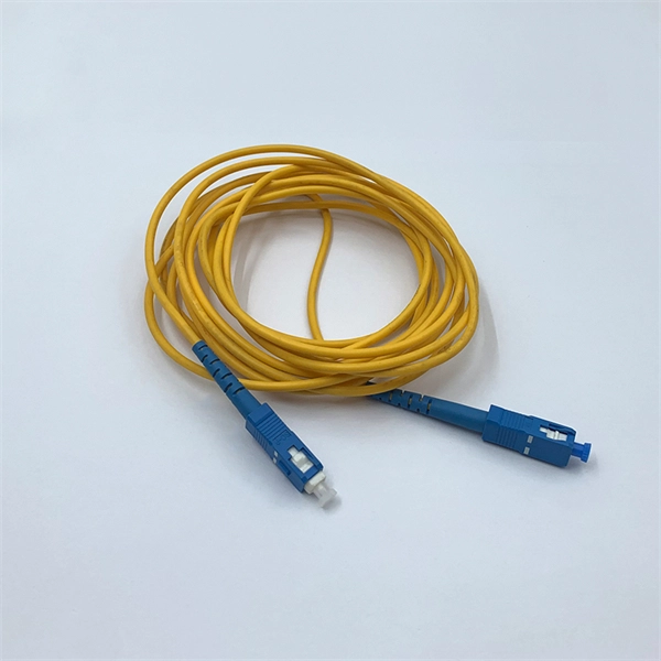
The protective outer layer, often called the jacket, surrounds the entire fiber optic cable. This layer is typically made from durable materials such as plastic, designed to protect the fragile core and cladding from external damage. Different types of cable are used for fiber-optic communication in different applications, for example long-distance. A fiber optic cable consists of five basic components: the core, the cladding, the coating, the strengthening fibers, and the cable jacket. When searching for a fiber optic cable, we need to pay attention not only to the connectors, such as SC to ST fiber cable, LC to SC fiber patch cable, or SC to. Fiber optic cables are made primarily of ultra-pure glass, specifically silicon dioxide (silica), the same compound found in quartz and ordinary sand. Each fiber is thinner than a human hair, yet it carries data as pulses of light across enormous distances. The materials are chosen for their clarity, flexibility, strength, and durability. What is Optical Fiber? Optical fiber consists of flexible glass or plastic strands engineered to transmit light. Manufacturers produce these fibers through a.
[PDF]
Our highly-skilled team of professionals specialize in the installation, termination, splicing, and testing of fiber optics technology in virtually every possible environment, including permitting services and challenging right-of-way deployments. Connect with local fiber optics experts now for seamless installation and future-ready connectivity. Fiber optics in San Jose provide advanced connectivity solutions crucial for modern communication and data needs. From Complex fiber panels and management to LAN. We can install new data centers, rebuild existing data centers, or fix pre-existing data centers. Our RCDD staff and manufacturer-trained personnel are happy to install, update, and sell our CAT5e/ CAT6/ CAT6a data cabling services to you. We also provide designs and engineering services for voice. Our company, located in the heart of the Bay Area, specializes in network cabling for all types of clients. Our team of skilled professionals have years of experience in cabling, networking, design, and installation. Our expert team specializes in top-tier Data Cabling and Network Wiring Installation, ensuring your business stays seamlessly connected. From initial consultation to final implementation, our solutions are designed to meet.
[PDF]
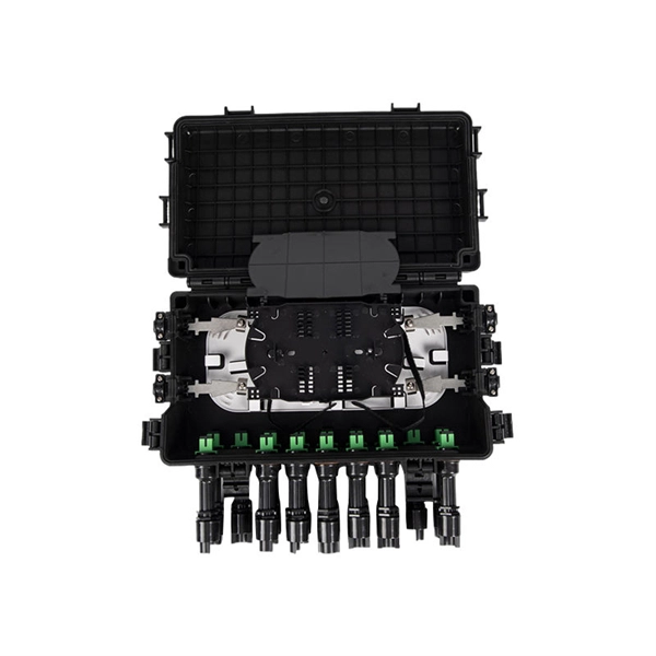
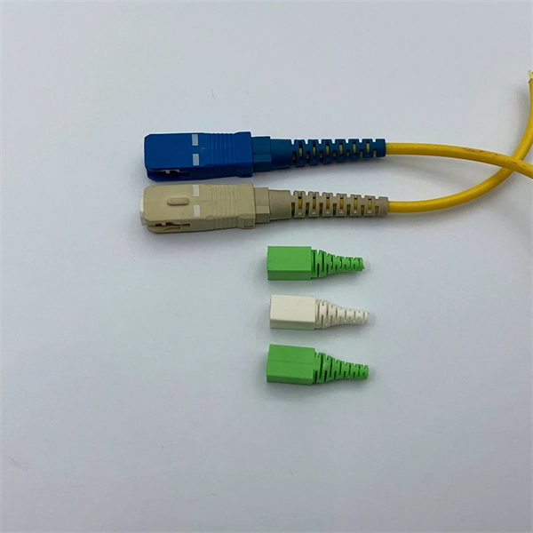
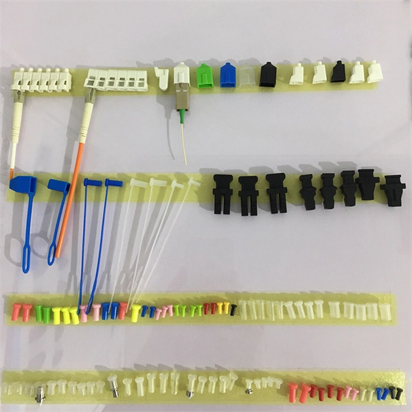
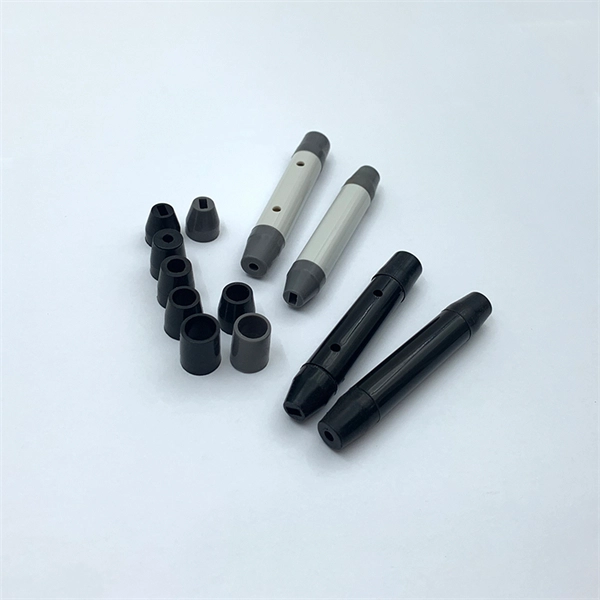
Pigtail, also known as pigtail, has only one end with a connector, and the other end is a broken end of a fiber optic cable core. It often appears in fiber optic terminal boxes. (couplers, jumpers, etc. are also used between. Long tail fibers consist of a phage-proximal and a phage-distal rod, each around 80 nm long and attached to each other at a slight angle. The phage-proximal rod is formed by a homo-trimer of gene product 34 (gp34) and is attached to the phage-distal rod by a monomer of gp35. are also used between them). One. The tailed phage T4 encodes a specialized device for this purpose, the long tail fiber (LTF), which allows the virus to move on the bacterial surface and find a suitable site for infection. Consequently, the infection efficiency of phage T4 is one of the highest, reaching the theoretical value of. Bacteriophages, often called phages, are viruses that infect and replicate within bacteria. These tiny biological entities play a significant role in microbial ecosystems. Tail fibers are structures on the phage that mediate their initial interaction with bacterial hosts, allowing them to recognize. The tail (Fig. Infection is initiated with the reversible attachment of six long tail fibers (LTFs) to the cell's outer layer of lipopolysaccharides, followed by transformation of the.
[PDF]
In a typical enterprise network architecture, the access layer switch is the first point of contact between end-user devices and the rest of the network. These switches connect endpoints such as PCs, printers, VoIP phones, and wireless access points, enabling user traffic to enter the LAN. It assists mainly in the switching of incoming and outgoing data packets to the right destination, as specified in MAC. In this layer, the layer 2 switches are installed to distribute the data packets to the addressed group of access devices. The layer 2 switches prevent over-crowding of data packets in transmission links and access devices. Wireless access points are also connected here and provide further access. FortiSwitch units distribute the ports to plugs. This layer serves as the network's outermost boundary and the gateway through which all data must pass. This layer is primarily composed of devices like access switches and wireless access points.
[PDF]

Selecting the right cable type ensures that the structure itself provides first-level protection. UV-Resistant Jackets (PE or LSZH): Prevent sunlight degradation. Water-Blocking Gel or Tape: Stops moisture migration inside the cable. Metal or Non-Metallic Armoring: Adds crush and. This guide covers how to safeguard outdoor fiber optics across underground, aerial, direct-burial, and exposed setups. Before applying protective measures, it's essential to understand the main risks fiber optic cables face outdoors. UV Exposure: Prolonged sunlight degrades standard plastic. Fiber optic cables are often used for long-distance communication due to their high bandwidth and low signal attenuation. Outdoor fiber optic cables are installed in harsh environments where they are exposed to various environmental factors such as temperature changes, humidity, moisture, dust, and. Optical cable lines lightning protection and strong current protection are achieved by avoiding, guiding or discharging them underground to prevent lightning and strong current from causing damage to the optical cable lines themselves, communication equipment and personnel. Since the lightning. The Fiber Optic Association, Inc. (FOA) was founded in 1995 to help develop the workforce to build the fiber optic networks to support a rapid expansion in communications and the Internet. Introduction: Why Fiber-Optic Cable Damage Matters Fiber-optic cables transmit data via pulses of light.
[PDF]
In 1880, and his assistant created a very early precursor to fiber-optic communications, the, at Bell's newly established in. Bell considered it his most important invention. The device allowed for the of sound on a beam of light. On June 3, 1880, Bell conducted the world's first wireless transmission between two buildings, some 213 meters apart. Due to its use of an atmospher.
[PDF]

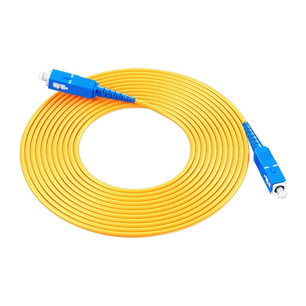
In fiber-optic communication, a single-mode optical fiber, also known as fundamental- or mono-mode, is an optical fiber designed to carry only a single mode of light - the transverse mode. Modes are the possible solutions of the Helmholtz equation for waves, which is obtained by combining. Single-mode fiber is a specialized type of optical fiber designed to transmit light along a single, narrow path, or “mode. ” This technology is foundational to modern digital communication, enabling the high-speed transfer of massive amounts of data over vast distances. This type of fiber is used for transmitting signals over long distances. It is specified as the best for especially long-distance applications than multimode fiber. This saves space and money. Dual fiber modules use two fibers. They are easier to set up and give steady communication. It comprises one glass or plastic fiber and features a tiny core of about 8-10 microns in diameter. This. There are two main types of fiber optic cables: single mode and multimode. Although they can do the same job in some instances, the different construction methods make each of them better suited to certain tasks and budgets.
[PDF]

Fusion Splicer Settings – Must-Know for Fiber Technicians! 🔧 At D-TECH TRADING, we're demonstrating the essential Fusion Splicer settings that every fi. more. Auto Mode is the most intuitive and user-friendly splice mode. The fusion splicer automatically detects the fiber type, such as single-mode (SM), multimode (MM), or dispersion-shifted (DS) fibers, and adjusts parameters like arc power and heating time accordingly. Applications: Ideal for beginners. Page 1 Fusion Splicer 19R+/70R+ Quick Reference Guide Splice Operation • When splicing only standard SM fibers (ITU-T G. 652), “SM AUTO” mode is recommended. It also outlines instructions for keypad usage. st Instruction manual Fusion Splicer Please read this instruction manual carefully before operating the equipment. Adhere to all safety instructions and warnings contained in this manual. Keep this manual in a safe place. There is a change without a previous notice. We are not responsible for the. Fusion splicing is the bedrock of high-performance fiber optic networks, enabling seamless signal transmission through permanent, low-loss fiber joins. As a leading provider of fiber optic infrastructure, Weunion leverages cutting-edge tools like the AI9 and AI10 fusion splicers, paired with.
[PDF]
A: Single mode fiber can typically transmit up to 160 km, and with dispersion compensation, it can exceed 200 km. Q: How far can multimode fiber go? A: The transmission distance of multimode fiber depends on the fiber type and data rate. However, for long-distance applications (e., metro and backbone networks), single mode fiber provides lower attenuation and future-proof scalability, resulting in lower long-term operational costs. For example, a fiber optic cable with a distance of 1km supports a bandwidth of 500MHz, while a fiber optic cable with a distance of 2km can only support a bandwidth of 250MHz. There are three main reasons for this: First, high-bandwidth. In the complex landscape of fiber optic infrastructure, selecting the right cable type—single-mode (OS1/OS2) or multimode (OM1/OM2/OM3/OM4/OM5)—can define a network's speed, reach, and cost-effectiveness. This guide dissects their technical nuances, evolution, and real-world applications. Fiber optic cable transmission distance is determined by two primary physical factors that affect signal quality as light travels through the fiber medium. Minimum Distance for Single-Mode Fiber: No Specific Limitation. Single-mode fiber is widely used in. Single-mode fiber (SMF): Uses a single light path, enabling it to transmit data over longer distances with less signal loss.
[PDF]
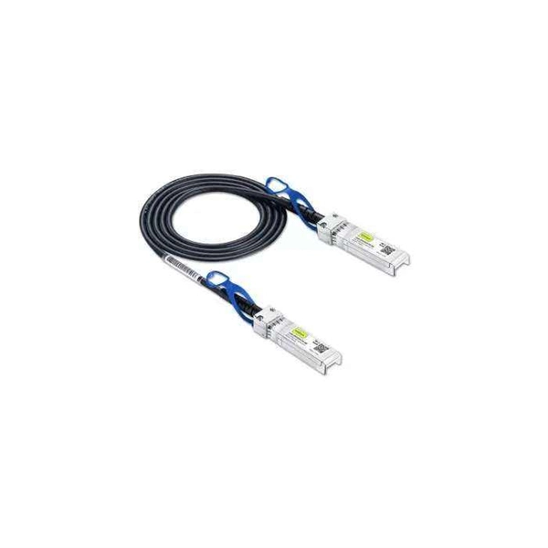
Single fiber modules (BiDi) use one fiber for both transmitting and receiving data. This saves space and money. Dual fiber modules use two fibers. They are easier to set up and give steady communication. In DWDM implementations, each direction of communication occupies a dedicated fiber, improving the stability of the transmission. This configuration is widely adopted in traditional telecom. Single-fiber WDM (also known as bidirectional or BiDi WDM) uses one physical optical fiber strand to transmit and receive signals simultaneously—often employing different wavelengths for upstream and downstream. How It Works: Two distinct wavelengths (e., 1270 nm and 1330 nm) are used in opposite. Single fiber module also called BiDi transceiver or WDM module. It uses WDM technology to realize the bidirectional transmission of optical signals on one optical fiber. BIDI module only has 1 port, wave filtering through the filter of module, and finished the transmitting of 1310nm optical signal. While both are designed for transmitting data over fiber optic cables, SFP bidi vs duplex differ significantly in how they operate and are deployed. In this article, we break down What Is an SFP BiDi Module and SFP Duplex Module? When Should You Use SFP BiDi and When Should You Use SFP Duplex? to. It has two distinct channels or ports, TX is used for transmission and RX for reception. For example: TX1310nm/RX1550nm TX1550nm/RX1310nm. Single fiber optical.
[PDF]