
Though the equipment using the fiber may have noisy fans that you could hear. Fiber optics do not emit any audible sound under normal operation. Fiber optic splicing is a foundational process that directly dictates the performance and reliability of data transmission. Two primary methods exist:. Fusion Splicing: This advanced technique uses an. The performance of a fiber optic splice is determined by a number of factors, including the quality of the fiber, the cleanliness of the splice, and the techniques used to make the splice. Intrinsic factors, such as the refractive index of the fiber, are those that are inherent to the fiber itself. Tech coming out on Sunday but my question is how does the fiber optic effect the tv service if it does at all? I've noticed lately how my cable signal has some noise and blurriness. Tech coming out on Sunday. The physics of noise in optical communication links is of great interest in the design of fiber optic communication systems. This can occur due to a number of factors, including excessive bending, crushing, or twisting of the cable. Damage to the cable can cause signal loss, poor performance, or even complete failure of the. With its greater bandwidth capacity and ability to transmit signals over long distances with very little power loss, fiber has become the hands-down favorite for the future of Broadband. Fiber's resistance to magnetic interference makes transmissions nearly noise free, and it has the advantage of.
[PDF]

Arduino Safety Relay Box With Wall Socket : A relay is an electrically operated switch. In this project there is no real need to isolate one circuit. Relay rooms are essential in modern commercial or industrial buildings, serving as secure enclosures for electrical relays that manage power distribution and automation systems. Designing a relay room requires balancing technical precision with safety, efficiency, and future scalability. Many relays use an electromagnet to mechanically operate the switch and provide electrical isolation between two circuits. In this article, you will learn how to design an electrical control cabinet for optimal safety and efficiency, following some. This handbook covers the code of practice in protection circuitry including standard lead and device numbers, mode of connections at terminal strips, colour codes in multicore cables, dos and donts in execution. Reliable components ensure system faultlessness and durability. Modern design and user-friendliness. equipment of most. This is Part 1 in a series of tutorials that will show you how to build a Bussmann RTMR fuse/relay block. If you're not familiar with this product, it's a simple waterproof enclosure that allows you to connect accessories on your vehicle through relays and/or fuses. After reading this tutorial, you.
[PDF]
Answer: The current transfer ratio (CTR) is an important parameter in optocoupler selection. The gain of an optocoupler is expressed as the Current Transfer Ratio (CTR). It is defined as the ratio of the phototransistor output current (Ic) to the LED input current (If), expressed as. The current transfer ratio is a parameter similar to the DC current amplification ratio of a transistor (h FE) and is expressed as a percentage indicating the ratio of the output current (I C) to the input current (I F). The CTR has the following characteristics and is therefore as important as the. An optocoupler, also known as photocoupler or opto-isolator, is a device which can transfer an electrical signal across two galvanically-isolated circuits by way of optical coupling. Transferring signals over a light. As I understand the optocoupler current transfer ratio, CTR is like the hfe of a transistor. I can't understand if the CTR is or isn't a critical value and for what applications is it used in. Optocouplers contain both a light-emitting diode (LED) and a photo detector. The current transfer ratio. The current transfer ratio (CTR) refers to the ratio of the collector current at the output side I c to the input current passed to the LED at the input side I F expressed as a percentage. It is defined by the following formula.
[PDF]
The 3R A3140 AA serves as a fully compatible, drop-in replacement for the HCPL-3140, featuring matched performance metrics including propagation delay, CMTI, and output current, ensuring dependable real-world implementation in industrial and automation settings. The HCPL-3140/HCPL-0314 family of gate driver optocouplers consists of an GaAsP LED optically coupled to an integrated circuit with a power output stage. These optocouplers are ideally suited for driving power IGBTs and MOSFETs used in motor control inverter applications. The high operating voltage range of the. 0. Here you can find various types and values of electronic parts from the world's leading manufacturers. The HCPL-3140/A3140 components of Jotrin Electronics are carefully chosen, undergo stringent. The HCPL-3140-000E is a 0.
[PDF]
Part two of this series provides details on how to build the beam splitter. It is made from regular float glass without any coating. Watch part 1 if you want. This article explains how to create a beam splitter cube in Sequential Mode. One of the biggest challenges for modeling such a system is that multiple ray paths cannot be simultaneously traced in Sequential Mode. Thus, multiple configurations are needed to trace rays along both the transmitted and. Beamsplitters are optical components used to split incident light at a designated ratio into two separate beams. Additionally, beamsplitters can be used in reverse to combine two different beams into a single one. Method A: Diffraction Grating surface and multi-configuration 2. Development steps Inserting general parameters for simulation (wavelength, aperture,. It is a crucial part of many optical experimental and measurement systems, such as interferometers, also finding widespread application in fibre optic telecommunications. In its. T E3 + RE4, where T; R are the transmission and re ection coe cients for the beam splitter. Note that jT j2 is the transmitted intensity. Similarly, E2 ! RE3 + T E4. The transformation matrix is then given by The elements of the beam splitter transformation matrix B are determined using the.
[PDF]

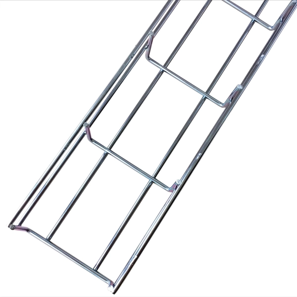
Professional Cable Tray Elbow Making | Metal Fabrication Tutorial Learn how to make cable tray elbows professionally with step-by-step guidance. This video shows metal fabrication techniques, DIY cable tray projects, and tips for perfect bends and joints. Whether you are a DIY enthusiast. The method for producing bridge bend elbows is as follows: Take a 90-degree cable tray bend elbow as an example, and apply the same principles for 45-degree bends accordingly. The length of the bottom side (bottom diagonal) after bending the cable tray should be equal to the width of the cable. This manual is designed to guide workers through the detailed production process of ladder cable trays, including the manufacture of horizontal elbows, tees, crosses, reducing bends, and vertical bends, with emphasis on precision, safety, and quality control. What's Involved in Producing Ladder. The bends, tees, crosses, risers and reducers of wire mesh cable tray can be easily and quickly made live at the project by using a bolt cutter. Since the jaws of the bolt cutter drags a layer of zinc across the cut end and forms a protective layer. When a wire cable tray is cut, the fact that a. How to bend 22. 5 DEGREE OF CABLE TRAY 3 LA. How to bend 90 degree of cable tray 3 line with the same distance :// • HOW TO BEND 90 DEGREE OF CABLE TRAY 3 LINE. Enjoy the videos and music you love, upload original content, and share it all with friends, family, and the world on YouTube.
[PDF]

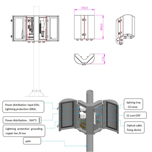
Check the electrical load and ensure that the sensors do not exceed the 10 Amp maximum. Check each wire for damage that may lead to a short. Check the tightness of electrical connections along the power. Issue: Frequent tripping of circuit breakers is one of the most common issues in distribution boards. It can occur due to overloaded circuits, short circuits, or ground faults. Solution: Identify the Cause: Check if the breaker is tripping due to overloading. Internal Inspection Open the distribution box and check for dust and debris accumulation. Inspect circuit breakers for proper operation. Ensure all connections are tight and secure. Each circuit breaker protects a specific circuit in your home, preventing excessive current from damaging wiring and. MDB is panel under power distribution system which consists of a fuse, circuit breakers and ground leakage protection units. Where electrical energy is taken from a transformer or an upstream panel to distribute electrical power to numerous individual circuits or consumer points. Various types of panels exist in every electrical.
[PDF]
