An electrical pigtail is a short piece of wire used to connect an electrical device, such as a switch or receptacle, to the main circuit conductors within a junction box. It acts as a jumper between the device terminal and the spliced bundle of circuit wires. This technique ensures the device is. Are a pigtail and a jumper wire the same thing, how are they different ? A jumper connects two devices or terminals together. Like you can jumper the top and bottom halves of a duplex receptacle if the bridge gets broken off. You can. The most intuitive difference between the two is that only one end of the pigtail has a connector, and both ends of the jumper have a connector. Optical Fiber Jumper: also known as optical fiber connector, both ends have connectors. Similar to coaxial cable, but without mesh shielding, for jumper. This detailed guide will take you through the basics of jumper wires, their types, applications, and the step-by-step process of connecting them securely and effectively. What Are Jumper Wires? Jumper wires are insulated wires used to connect two points in a circuit. They usually come with. Pigtails play a crucial role in ensuring safe and efficient connections within electrical systems, especially when dealing with multiple wires or limited space. Understanding what a pigtail is and how it works can make your wiring projects smoother and safer.
[PDF]
This is the FOA's Online Guide To Fiber Optics, Fiber Broadband & Premises Cabling. With 19+ years of experience installing fiber-optic cables at over 20,000 locations, we've seen how prices vary based on cable type, project scope, and installation complexity. Fiber-optic cable materials typically cost $1 to $6 per linear foot, depending on fiber count and cable type. Main cost drivers include cable grade (indoor vs outdoor, armoured), distance, and labor for trenching, splicing, and termination. This guide presents ranges in USD and practical price estimates to help. Fiber optic cables are essential components in today's broadband, FTTx, and data center networks. Whether you're planning a national fiber rollout or sourcing cables for enterprise infrastructure, understanding how fiber optic cable pricing works can help you budget more effectively and make better. We have included Per Foot conversions for reference (1 Meter ≈ 3. Best For. * Disclaimer: Prices fluctuate based on raw material indices (Glass/Copper/Polymer) and cable core count (e. These cables, constructed with glass or plastic fibers, transmit data through light pulses, offering.
[PDF]

The video tutorial demonstrates the depin and repin method for repairing automotive wiring harness connectors, specifically pigtails. It outlines seven easy steps to replace a pigtail connector, making it accessible for DIY enthusiasts and individuals dealing with electrical issues. This comprehensive guide will equip you with the knowledge and skills to accurately assess the integrity of a pigtail, helping you identify issues before they escalate into larger problems. We'll explore different testing methods, delve into the interpretation of multimeter readings, and offer. The latest in the line of Ford Flex Probe Kits, this newest release includes all the probes from the previous “D” kit, but now adds two each of the Micro Pin (. Additionally, all probes will now be printed with the tip size, helping technicians ensure usage of the properly sized tip. Short answer: An automotive wiring pigtail is a short section of wire with a pre-attached connector that lets you repair or replace a damaged plug without replacing the entire harness. It provides a plug-and-play repair solution that restores OEM fit, seal, and electrical reliability. Key steps. At FindPigtails. com, we specialize in high-quality, OEM connector replacement. Why pay thousands for a complete wire harness, when you can simply replace the damaged connector? We invite you to take a look at some of our instructional videos, for step-by-step guides of de-pin and re-pin procedures.
[PDF]

In this video, we'll walk you through the process of wiring a home distribution box with a detailed connection diagram. Whether you're an electrician or a DIY enthusiast, this guide will help you understand the basics of home electrical distribution. more Welcome to our channel! In this video. Single Phase wiring installation is the most common wiring in residential buildings. In Single Phase supply (230V in UK, EU and 120V & 240V in the US & Canada), there are two (one is Line (aka Phase, Hot or Live) and the other one is Neutral) incoming cables from the utility poles to the kWh energy. A distribution board or distribution box is where the main power supply is distributed to multiple loads. And all the switching and protective devices are installed in the distribution box. Single Phase Distribution Box generally consists of Double Pole MCBs, Single Pole MCBs, and RCCBs. An electrical panel box, also known as a breaker box or a distribution board, is a crucial component of any electrical system. It serves as a central hub for distributing electricity throughout a building, ensuring that power is delivered safely and efficiently to all the required locations. What is Distribution Board? Distribution board.
[PDF]
Basic run: 800 ft outdoor fiber drop with aerial installation, minimal trenching, and standard termination. Labor: 12–18 hours; Materials: $1,200; Total: $3,500-$6,000. Homeowners and businesses typically pay for fiber optic cable installation based on distance, conduit needs, and labor. The main cost drivers include material type, run length, trenching or aerial work, and any required permits or inspections. This article provides cost. A simple 1-core FTTH drop cable costs around $0. 13 per foot, while a 288-count optical fiber cable for building backbones can reach $6 per foot or more. Pre-terminated assemblies and patch cables incur higher costs due to factory termination, with prices varying by connector type and the number of. Whether you need singlemode, armored, or indoor plenum, this guide gives you the exact cost per foot of fiber optic cable — including installation — so you can budget without guesswork. Data aggregated from Q1 2026 contractor invoices across Texas, Ohio, and North Carolina. Understanding cost ranges helps buyers budget. Cost of Laying Fiber Optic Cable in the U. The price ranges reflect both ongoing improvements in fiber deployments and regional differences in permitting and crew rates.
[PDF]

Cable Trays* — Max two 24 in. (610 mm) wide by max 6 in. (151 mm) deep open-ladder cable tray with channel-shaped side rails formed of 0. 54 mm) thick aluminum or min 0. In practice, cable tray dimensions are a system of interrelated measurements —width, depth, length, and material thickness—that directly affect cable fill compliance, heat dissipation, structural loading, and long-term expandability. From an engineering standpoint, cable tray dimensions are not. Perforated Cable Tray System expertly constructed from high-grade stainless steel, offering exceptional durability and resistance to corrosion. With side height 100mm. A properly designed and installed cable tray system will provide. Studs — Wall framing to consist of wood studs or channel shaped steel studs. Wood studs to consist of nom 2 by 4 in. Additional studs shall be used to completely frame. Best Size: Here, deep trays (75mm to 150mm) are used since power cables are typically thick and heavy. Data cables, such as your Wi-Fi or computer ones, are extremely sensitive. They do not get hot; however, they do not like to hang or sag. In case a data cable folds in an excessive manner, the. ect the minimum bend ra-dius for cables as they exit the bottom of the cable tray. A rung spacing of 6 to 9 inches (150 to 230 mm) is preferable when the cable tray cont d for instrumentation and control applications that require additional protec eferred to support and protect numerous small.
[PDF]
will introduce major upgrades to its Multi-Rail technology platform at ECOC 2025, targeting hyperscale optical transport with new efficiency, scale, and performance enhancements. Coherent Corp. SAXONBURG, PA, September 26, 2025 (GLOBE NEWSWIRE) – Coherent Corp. At the heart of the. SAXONBURG, Pa. At the heart of the. Simultaneously, coherent technology has emerged as the prevailing solution for Data Center Interconnection (DCI) applications, covering distances of 80~120km in the field of data communication. These evolving applications introduce new demands for coherent optical transceiver systems, steering the. Coherent optical module refers to a typically hot-pluggable coherent optical transceiver that uses coherent modulation (BPSK / QPSK / QAM) rather than amplitude modulation (RZ/ NRZ / PAM4) and is typically used in high-bandwidth data communications applications. Optical modules typically have an.
[PDF]

Plug an SEL-2810 Fiber-Optic Transceiver With IRIG-B directly into a standard 9-pin serial connector (DB-9). No special mounting is required. The SEL-2810 receives power from the host device via the connector; no separate power supply or power wiring is needed. It also requires no. Improve safety, signal integrity, and reliability by using optical fiber instead of wire for instrumentation, protection, automation and other applications that benefit from economical fiber-optic links up to ½ kilometer long. Fiber-Optic Link— Establish EIA-232 communication between devices over a. The RLH Contact Closure Fiber optic converter transmits 8 digital input signals over fiber optic cable. Applications include alarm event triggering, building automation, environmental control systems, fire & alarm systems, gate control, traffic signal control equipment, and more. Use two optical fibers instead of 32 wires between outdoor or remote equipment and the control building to reduce costs, improve safety, and boost reliability. SFP transceivers bridge electrical and optical signals, making them indispensable in data centers, telecom networks, and.
[PDF]
Explore key factors affecting electrical busbar prices, market trends, and tips for smart purchasing to optimize cost and quality in power systems. From copper busbar and aluminum busbar options to insulated busbar and busbar trunking systems, our Busbar Products Pricing Guide helps you balance quality, durability, and budget to make the right choice. Yet many electrical contractors, facility managers, and industrial buyers struggle with one. Busbar trunking systems are essential components in modern electrical distribution networks, offering efficient, reliable, and scalable power delivery across commercial, industrial, and institutional facilities. However, their pricing can vary significantly based on several technical, material, and. Comparing busbar trunking system prices. The Vertiv™ Powerbar patented range of busbar trunking ads overhead power distribution to your data center, allowing increased accessibility to power loads for maintenance. Circuits can be added and removed easily as they are located just above their respective racks. This allows you to make. The global busbar trunking system market is experiencing steady growth, driven by industrial automation, infrastructure development, and demand for energy-efficient electrical distribution. According to Grand View Research, the market size reached $6.
[PDF]

An Optical Splitter, also known as a beam splitter, is a passive optical device that divides a single input optical signal into two or more output signals. Conversely, it can also combine multiple signals into one. Knowing the difference between a splitter and an optical coupler helps you build better networks. You make your network work better when you pick the right device for each job. You can connect many users to one port with 1:n or 2:n splitters. By dividing a single optical signal from a central Optical Line Terminal (OLT) into multiple outputs for Optical Network Terminals (ONTs) at users' homes, splitters eliminate the need for dedicated fibers to each residence—slashing infrastructure costs while scaling network reach. This guide. In a Passive Optical Network (PON), a single optical fiber carries massive amounts of data using light. Signal Input: The fiber splitter receives the optical signal from the upstream network node and enters the splitter through the input fiber. Signal Distribution: Inside the splitter, according to the design structure and different. Splitters are passive optical devices that divide or combine optical signals, and they come in various types, including power splitters, uneven splitters, and wavelength-division multiplexing (WDM) splitters. Each type serves specific applications, enabling efficient use of optical infrastructure.
[PDF]
In this informative video, learn how to seamlessly integrate fiber optic cables with Power over Ethernet (PoE) systems for enhanced connectivity and performance. This installation guide focuses on what a patch panel does, patch panel installation basics, and how to connect patch panel to switch while keeping cabling clean and easy to manage. Switch: What's the Difference? Although a patch panel and a switch can look similar in a rack, they. Fiber patch panels are important components that are used to help organize and protect fiber optic cables. Connecting a fiber patch panel to a switch is a critical step in setting up a fiber optic network. Identify. If the PoE switch has SFP slot built-in, what you need is the SFP module installed in the slot. Firstly, Insert the SFP module into PoE switch's SFP slot. Discover the advantages of using fiber optic cables in conjunction with PoE and gain insights into the necessary components required for. If you have an existing patch panel the short answer to “can I just plug in a cable into the front of it” is yes. In comparison to wiring up individual networks, patch panels are much more efficient and can provide more reliable, faster connections. This article will.
[PDF]
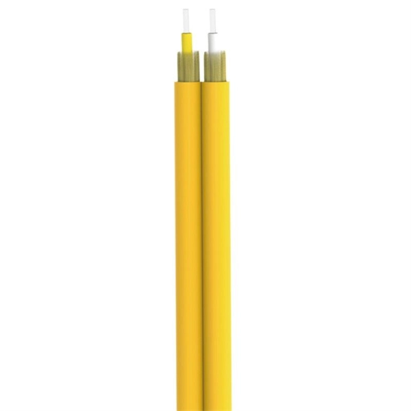
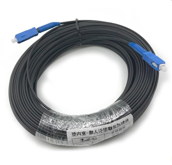
Learn about the differences between fiber optic pigtails and fiber patch cords, types of fiber pigtails and how to test connectors. In the intricate ecosystem of fiber optic networks, two components play a critical role in ensuring seamless connectivity: patch cords and pigtails. While both are essential for linking fibers to devices or other cables, they serve distinct purposes and are designed for specific scenarios. When you build or upgrade a fiber network, the same four words pop up everywhere— fiber optic (bare fiber), pigtail, patch cord, optical cable. They're related, but they are not interchangeable. Mixing them up drives costs higher, increases loss, and slows your rollout. The good news? Once you nail. Today, I'll show you how to pick the right patch cord or pigtail — step by step. A Fiber Patch cord connects two devices. You plug it into a switch, router, or patch panel. A pigtail is for splicing. What Is a Fiber Optic Patch Cord? A. When it comes to fiber optic products, it's essential to differentiate between patch cords and pigtails as they serve distinct purposes in optical communication systems. The. Our LC duplex zipcord fiber optic patch cord offers reliable, high-speed connections for voice, data, or video in data centers, offices, and telecom rooms, with fire-retardant options.
[PDF]
This video makes connecting your fiber optic cable to your router a breeze! We'll guide you through the entire process step-by-step, ensuring a smooth and hassle-free experience. Our Experts are helping user's, who are facing issues with their tech gadgets like. In this guide, we'll walk you through how to connect a fiber optic cable to a router safely and efficiently. Why Use Fiber Optic Internet? Before diving into the setup, let's quickly recap why fiber optics are worth the effort: Lightning-fast speeds (up to 1 Gbps or higher). Low latency for. Connect an Ethernet cable from the WAN port of your router to a LAN port on the Internet source (such as a broadband modem or fiber-optic modem). If you. This conversion happens either through an Optical Network Terminal (ONT) or directly via specialized router ports. Check compatibility: Before you begin, make sure your router supports fiber optic connection. Not all routers can connect directly to a fiber cable, so it is important to verify this information before continuing. Here's a step-by-step guide to help you through it. Understand the Basics Before diving in, familiarize yourself with the components involved:.
[PDF]
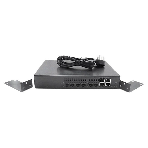
Fiber optic switches are devices used to control the flow of light in fiber optic networks. They are used in a wide range of applications, including telecommunications, data centers, industrial automation, and military and aerospace. This piece analyzes how these switches can make a difference today. Fiber optic switches offer numerous advantages over traditional. A fiber optic switch is an electronic device that allows multiple fiber optic cables to be connected and selectively route data between them. The switch receives data packets from one input fiber optic cable and forwards them to the appropriate output cable based on their destination addresses. It operates on the same principle as an electrical switch, but instead of using electrical signals, it uses light signals to switch data packets from one fiber optic cable to another. Fiber. A fiber optical switch, also known as a fiber channel switch or a SAN (Storage Area Network) switch, is a high-speed network transmission relay device. This technology offers significant.
[PDF]

An optical coupler helps split or join light signals in a fiber network. It can take one light signal and send it to two or more places. They do not send signals to the. An Optical Splitter, also known as a beam splitter, is a passive optical device that divides a single input optical signal into two or more output signals. Unlike active devices (which require power), splitters operate without electricity, relying solely on the physics of. You use optical couplers and splitters to split or join signals in fiber networks. For example, optical splitters send light to many output ports. This lets you connect more users to one network terminal. You can also use them to join light from. Optical Distribution Network (ODN) - The physical fibre and optical devices that distribute signals to users in a telecommunications network. The ODN is composed of passive optical components (POS), such as optical fibers, and one or more passive optical splitters. Optical Network Termination (ONT). Functioning as a translator, the ONT converts optical signals from the fiber optic cable into electrical signals that your router and devices can understand. In essence, it serves as the bridge between your internet service provider's (ISP) network and your home network. This type of device plays an important role in passive.
[PDF]
