The BA-1 device produces step attenuation of a laser beam to a maximum of about 44 dB . With the preattenuator beam splitter, denoted by SI, this range can be extended as much as another 3 0 dB. The various low level beams generated by BA-1 can be used for detector respon-sivity and. Danielson, B. (1977), Measurement procedures for the optical beam splitter attenuation device BA-1:,, National Institute of Standards and Technology, Gaithersburg, MD, , https://doi. 77-858 (Accessed February 10, 2025) If you have any questions about this publication or. Beam splitters are optical devices that play a crucial role in various scientific and industrial applications. They are used to divide a beam of light into two or more separate beams. NBS interagency report is a publication of the U. The papers are in the public domain and are not subject to copyright in the United States. The BA-1 system is designed for use at. The attenuation ratios of these wavelengths are calculated values. An analysis of the estimated uncertainties is. SPLITTER ATTENUATION DEVICE BA-1 B. Danielson Measurer::ent procedures are described for the step attenuation of laser bearriS up to 44 dB using a specially constructed attenua- tor box (BA-1). a laser beam) into two (or sometimes more) beams, which may or may not have the same optical power (radiant flux).
[PDF]

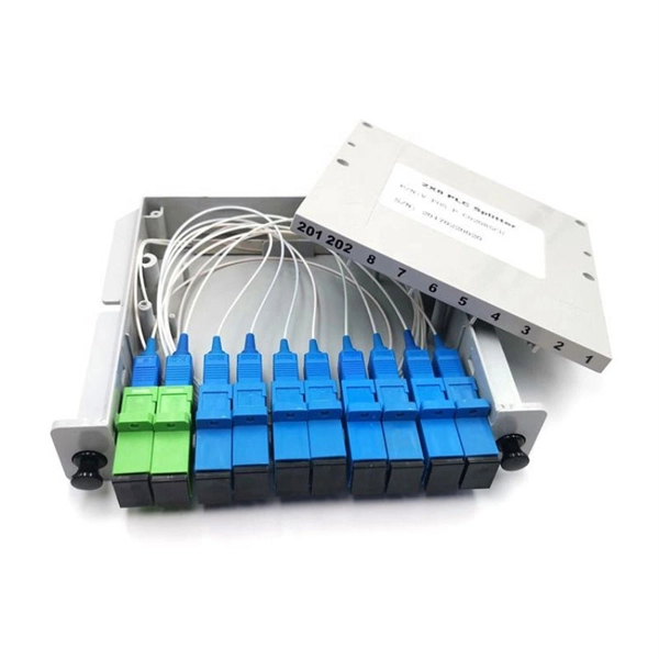
Attenuation describes the continuous loss along the fiber, while insertion loss describes the additional loss caused by components such as connectors, splices, or splitters. In fiber optic networks, particularly in FTTx (Fiber to the x) and PON (Passive Optical Networks) deployments, splitters play a central role in distributing the optical signal from a single source to multiple destinations. The split ratio and insertion loss are two key parameters defining their performance. A deeper understanding of these. This document describes how to calculate the maximum attenuation for an optical fiber. You can apply this methodology to all types of optical fibers in order to estimate the maximum distance that optical systems use. There are no specific requirements for this document. This document is not. By dividing a single optical signal from a central Optical Line Terminal (OLT) into multiple outputs for Optical Network Terminals (ONTs) at users' homes, splitters eliminate the need for dedicated fibers to each residence—slashing infrastructure costs while scaling network reach. Losses can be introduced by various means such as intrinsic material absorption, scattering, bending, connector loss and more. The tutorial has the following parts: When light propagates as a guided wave in a fiber core, it experiences some power losses. These are particularly important for long-haul data transmission through fiber-optic telecom.
[PDF]

If we have measured gains in linear units (e. in Watts – W), the loss value in dB is calculated by the formula: Loss (dB) = 10 lg ( mW1 / mW2 ) When both gains are equal, the loss is 0 dB, so there is no loss (doesn't happen obviously). If we operate with absolute gains measured in relation to 1. They are used to divide a beam of light into two or more separate beams. Depending on the design, beam splitters can either reflect a portion of the incoming light and transmit the remainder or split light based on polarization. For a lossless beam splitter, R + T = 1. The numbers can differ. ♦ How to calculate the optical attenuation in a passive optical network (PON)? In PON equipment, the maximum attenuation value of OLT is between 22-25dB, which means that the attenuation value cannot exceed 25 dB. 1:2 PLC splitter attenuation is 3. 03 dB 1:16. Let's say you have a laser output at 0 dBm (which is 1 milliwatt of optical power). 5 dB of insertion loss, the power at each output would be: 0 dBm – 10. 089 mW (less than a tenth of the. Fiber optic splitters generally consist of an input port and several output ports and are categorized into two types based on their operating principles: coupling type and beam splitter type. Coupling-type splitters use optical couplers to divide optical signals, while beam splitters employ.
[PDF]
A beam splitter or beamsplitter is an optical device that splits a beam of light into a transmitted and a reflected beam. It is a crucial part of many optical experimental and measurement systems, such as interferometers, also finding widespread application in fibre optic telecommunications. DesignsIn its most common form, a cube, a beam splitter is made from two triangular glass which are glued together at their base using polyester,, or urethane-based adhesives. (Before these synthetic,. Beam splitters are sometimes used to recombine beams of light, as in a. In this case there are two incoming beams, and potentially two outgoing beams. But the amplitudes. For beam splitters with two incoming beams, using a classical, lossless beam splitter with Ea and Eb each incident at one of the inputs, the two output fields Ec and Ed are linearly related to the inputs thro.
[PDF]
They can be used to split unpolarized light at a 50/50 ratio, or for polarization separation applications such as optical isolation (Figure 3). Non-polarizing beamsplitters split light into a specific R/T ratio while maintaining the incident light's original polarization state. A beam splitter or beamsplitter is an optical device that splits a beam of light into a transmitted and a reflected beam. It is a crucial part of many optical experimental and measurement systems, such as interferometers, also finding widespread application in fibre optic telecommunications. In its. 📦 For purchasing, use the RP Photonics Buyer's Guide for beam splitters. It provides an expert-curated supplier directory, buyer-focused technical background information, and structured selection criteria to support professional procurement decisions. What are Beam Splitters? A beam splitter (or. Returning light from the sample goes through the same objective and beam splitter, through a pinhole and into a detector (typically a scientific camera). Beamsplitters are often classified according to their construction: cube or plate. An alternative is the acousto-optical beam splitter (AOBS) which has freely tunable reflection notches. On average 95% of the emitted light is transmitted between these narrow notches.
[PDF]
While most beam splitters have a fixed splitting ratio, variable beam splitters allow for the continuous adjustment of the ratio between reflected and transmitted power. Signal attenuation refers to the reduction in the intensity of a light beam as it passes through a medium or a device. When a beam splitter divides the incoming light. A beam splitter (or beamsplitter, power splitter) is an optical device which can split an incident light beam (e. a laser beam) into two (or sometimes more) beams, which may or may not have the same optical power (radiant flux). It is a crucial part of many optical experimental and measurement systems, such as interferometers, also finding widespread application in fibre optic telecommunications. In its. A pellicle beamsplitter may appear to solve these problems by stretching an elastic membrane (sometimes coated) over a metal frame until it is very thin, but in reality, coating options are limited, and they offer lower power handling than cube beamsplitters. These exiting beams are differentiated by either their optical power (non-polarizing) or polarization states (polarizing). Non-polarizing beamsplitters are specified by their splitting ratio, i.
[PDF]
Connectorized attenuators often have a quite compact housing, essentially looking like a fiber-optic adapter. Some of these devices provide a fixed level of attenuation, quantified as the insertion loss in decibels. An optical attenuator, or fiber optic attenuator, is a device used to reduce the power level of an optical signal, either in free space or in an optical fiber. The basic types of optical attenuators are fixed, step-wise variable, and continuously variable. Optical attenuators are commonly used in. Fiber-optic attenuators are a specific type of optical attenuators which are used in fiber optics, e. for achieving a suitable signal level for a data receiver in a telecom system. It primarily ensures the power or amplitude of a signal is lowered without significantly distorting its waveform. The attenuator circuit will allow a known source of power to be reduced by a predetermined factor, which is usually expressed as decibels.
[PDF]

5 dB depending on splitter type. Common planning value: 0. Optional: patch panels, attenuators, or extra components. Helps cover dirt, aging, and measurement tolerances. Adds Rx power and margin calculation. Use 2×N when two inputs feed the same distribution stage. Wavelength is recorded in outputs for documentation. Optional: patch. FTTH / PON Splitter Loss Calculator - Zion Communication is a professional manufacturer of cables and accessories for signal and low voltage transmission. Estimate whether an FTTH or PON optical link is feasible by calculating PLC splitter loss, fiber attenuation, connector loss, splice loss and. In fiber optic networks, particularly in FTTx (Fiber to the x) and PON (Passive Optical Networks) deployments, splitters play a central role in distributing the optical signal from a single source to multiple destinations. These are known as passive optical splitters, and they perform the function. The formula for the theoretical loss for each output port of a splitter with N output ports is: Theoretical Split Loss (in dB) = 10 * log10 (N) Where: N is the number of output ports the splitter has (e., 2 for a 1x2 splitter, 4 for a 1x4, 8 for a 1x8, 32 for a 1x32, etc. Passive split links usually lose the most dB at the splitter, so we keep the optical budget and the installed route separate. These are especially important for FTTH (Fiber to the Home), data centers, and Passive Optical Networks (PON), where.
[PDF]
The NanoSpeed™ Series 1×4 solid-state fiber-optic splitter splits the optical power among four outputs with any power splitting ratio. The input is polarization-maintaining (PM) fiber and the outputs are four single mode or PM fibers. Thorlabs offers a wide range of optical beamsplitters. Our plate beamsplitters have a coated front surface that determines the beam splitting ratio while the back surface is wedged and AR coated in order to minimize ghosting and interference effects. Pellicle beamsplitters provide excellent. Beamsplitters are optical components used to split input light into two separate parts. Beamsplitters are also ideal for fluorescence applications, optical interferometry, or life science or semiconductor instrumentation. Light. PLC (Planar Lightwave Circuit) Splitters are designed for single-mode applications and offer an even split ratio from one input fiber to multiple output fibers. Circular beamsplitters, plate beamsplitters and cube beamsplitters can be purchased for polarizing or non polarizing beamsplitting. OZ Optics Online. This is achieved using patent pending non-mechanical.
[PDF]
Also, please take a look at the list of 42 beamsplitter manufacturers and their company rankings. ORAFOL Fresnel Optics GmbH, 2. Newport Thin Film Laboratory, 3. Haas Laser Technologies, Inc. What Is a Beamsplitter?. PPC Broadband offers a range of optical splitters designed for various applications, including indoor and outdoor use. Their expertise in fiber solutions for telecommunications ensures high-quality performance in connectivity technology. OptiWorks is a prominent manufacturer of fiber optics. Welcome to this comprehensive resource for Optical Splitters Suppliers and Manufacturers on Thomas. Here you can find any Optical Splitters Suppliers that suits your needs. A simple beamsplitter may be a very thin sheet of glass inserted in the beam at an angle to divert a. Use this beam splitters buying guide to compare major types, define selection criteria, and find suppliers: 🔬 Encyclopedia article: beam splitters 📦 Top-level product category: optical components and devices Click on a logo to get to the details of that supplier's offer. Our list of suppliers for. WELL BUILT - Durable PVC outer layer, low-jitter optical fibe provide higher fidelity sound and good listening experience. e Precision polished 24K Gold Plated Connector gives optimal signal transfer accuracy. TIGHT FIT - The splitter provides a firm connection of Toslink cables by clicking in.
[PDF]
A beam splitter or beamsplitter is an that splits a beam of into a transmitted and a reflected beam. It is a crucial part of many optical experimental and measurement systems, such as, also finding widespread application in.
[PDF]

With the large variety of beamsplitters available, the designer needs to take many factors into consideration. This article and its illustrations will go a long way toward making the correct choice less of a risk. All curves show typical performance. A beam splitter (or beamsplitter, power splitter) is an optical device which can split an incident light beam (e. a laser beam) into two (or sometimes more) beams, which may or may not have the same optical power (radiant flux). It is a crucial part of many optical experimental and measurement systems, such as interferometers, also finding widespread application in fibre optic telecommunications. One beam is typically reflected while the other is transmitted. Beamsplitters are often classified according to their construction: cube or plate. In this blog, we will explore the step-by-step process of using a beamsplitter cube effectively, along with some common applications that benefit from this powerful optical tool. Step-by-Step Guide on Using a Beamsplitter Cube Step 1: Understanding the Cube Orientation: A beamsplitter cube is a. A beam splitter is an optical device that splits beams (such as laser beams) into two (or more) beams. Beam splitters typically come in the form of a reflective device that can split beams into exactly 50/50, half of the beam being transmitted through the splitter and half being reflected.
[PDF]
A beam splitter or beamsplitter is an optical device that splits a beam of light into a transmitted and a reflected beam. It is a crucial part of many optical experimental and measurement systems, such as interferometers, also finding widespread application in fibre optic telecommunications. DesignsIn its most common form, a cube, a beam splitter is made from two triangular glass which are glued together at their base using polyester,, or urethane-based adhesives. (Before these synthetic,. Beam splitters are sometimes used to recombine beams of light, as in a. In this case there are two incoming beams, and potentially two outgoing beams. But the amplitudes. For beam splitters with two incoming beams, using a classical, lossless beam splitter with Ea and Eb each incident at one of the inputs, the two output fields Ec and Ed are linearly related to the inputs thro.
[PDF]
In this work, we extend these fundamental properties to measures of similarity between states, provide inequalities for creation and annihilation operators beyond the Cauchy-Schwarz inequality, prove a conjecture [Hertz et al., PRA 110, 012408 (2024)] dictating that nonclassicality. A beamsplitter is a common optical component that partially transmits and partially reflects an incident light beam, usually in unequal proportions. In addition to the task of dividing light, beamsplitters can be employed to recombine two separate light beams or images into a single path. This. Beamsplitters separate incident light into two or more beams of the same wavelength. These exiting beams are differentiated by either their optical power (non-polarizing) or polarization states (polarizing). It is a crucial part of many optical experimental and measurement systems, such as interferometers, also finding widespread application in fibre optic telecommunications. Conversely, it can also combine multiple signals into one. Its primary role is in Passive Optical Networks (PON), which are the foundation of. Our recent proof for the entanglement properties of states interfering with the vacuum on a beam splitter led to monotonicity and convexity properties for quantum states undergoing photon loss [Lupu-Gladstein et al. 03423 (2024)] by breathing life into a decades-old conjecture.
[PDF]
Beamsplitters are optical components used to split incident light at a designated ratio into two separate beams. They can also be used in reverse to combine two or more separate beams into a single one. This precise ability to split light by wavelength makes beam splitters essential in various fields, including laser systems, semiconductor. A beam splitter is an optical device that splits beams (such as laser beams) into two (or more) beams. Beam splitters typically come in the form of a reflective device that can split beams into exactly 50/50, half of the beam being transmitted through the splitter and half being reflected. 2. Beam Splitters separate incoming light into two beams. In reverse, they combine. Can be metallic, dielectric or a mix & rejected light absorbed, reflected or both. Beam Splitter (BS) is a term used to describe various. A plate beamsplitter (one face antireflection coated, the other face thinly aluminized) will work essentially the same way: the transmitted-to-reflected beam ratio will be the same regardless of whether the beamsplitter is used in the forward or backward mode. I am upvoting the answer by S.
[PDF]