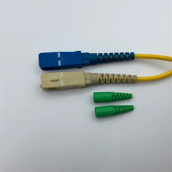
Explore our comprehensive SFP optical module selection guide for 2025. Learn about crucial factors like data rate, distance, fiber type, and compatibility to optimize your network performance and cost-effectiveness. Make informed decisions for your networking needs today!. SFP (Small Form-factor Pluggable) is a compact, hot-pluggable network interface module used to connect network devices (switches, routers, firewalls) to fiber optic or copper cables. They're essential for extending network distances and increasing bandwidth capabilities. Selecting the correct SFP module is not simply a matter of matching connectors. In modern Ethernet networks, choosing the wrong transceiver can result in link failures, speed mismatches, compatibility errors, or unexpected distance limitations. For network engineers, system integrators, and IT. At the core of these advanced networks are bidirectional SFP modules, also known as BiDi SFP transceivers—compact, cost-efficient devices that support high-speed data transmission and reception over a single optical fiber. By using different interfaces and single-mode or multimode fiber depending on the.
[PDF]
Recommendation ITU-T L. 163 describes criteria for the installation of optical fibre cables defined in Recommendation ITU-T L. 110 in remote areas with lack of usual infrastructure for installation including the procedures of cable-route planning, cable selection, cable-installation. The Fiber Optic Association, Inc. (FOA) was founded in 1995 to help develop the workforce to build the fiber optic networks to support a rapid expansion in communications and the Internet. The charter of the FOA was to promote professionalism in fiber optics through education, certification, and. specifications under which the various work for trenching & laying of optical fiber cable are to be executed by the Vendor. The broad guidelines as laid down by TEC India, for laying of OFC networks are to be followed. Underground cables are pulled in conduit that is buried underground, usually 1-1. 2 meters (3-4 feet) deep to reduce the likelihood of accidentally being dug up. In extreme cold climates, cables may need to be buried at greater depths where there. If we can reduce failures and increase the service life of optical cables by carrying out communication optical cable construction in a standardized manner, it is worth understanding and learning for us telecommunications construction workers. To this end, overhead optical cable construction.
[PDF]
In this guide, we'll break down everything you need to know to install a distribution box correctly and confidently. Choose the right box based on environment (indoor/outdoor), load capacity, and durability. Check for proper IP/NEMA ratings and material quality. A distribution box is the heart of any electrical system. It takes the incoming power and safely distributes it to different circuits throughout your building. Whether in a home or an industrial facility, this box keeps your electrical setup organized, functional, and efficient. However, the key to. In modern electrical systems, cable distribution boxes (also known as electrical distribution boxes or distribution boxes) play a crucial role as the key hub for managing, distributing, and protecting circuits. Just like travelers need clear pathways and safety protocols, your electrical circuits need proper management to prevent chaos. This article details the process of installing them, which helps you comprehend distribution boxes. Learn how to wire a distribution box step by step! This video shows real on-site footage of electrical installation, demonstrating safe and standardized wiring methods used by professionals. Site selection requirements: The distribution box should be installed in an area close to the power supply to reduce.
[PDF]
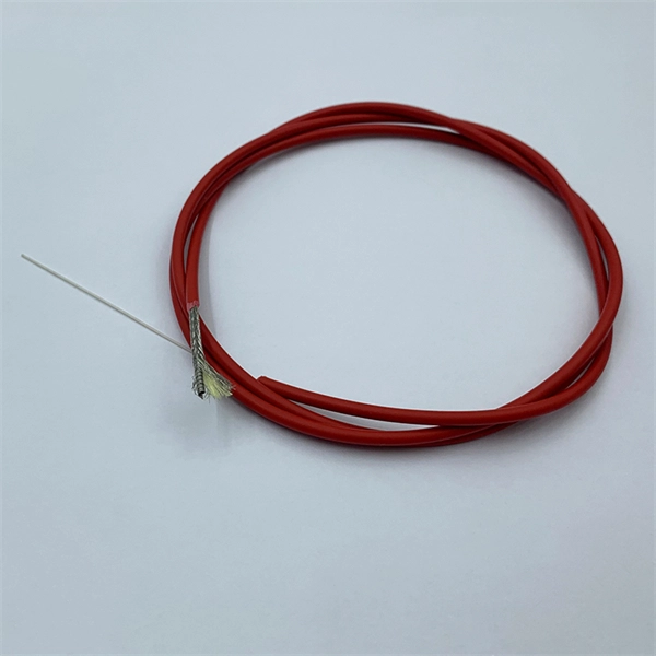
This is the latest revision of this Recommendation that was first created in 1988. Recommendation ITU-T G. 654 describes the geometrical, mechanical and transmission attributes of a single-mode optical fibre and cable which has the zero-dispersion wavelength around 1300 nm wavelength, and which is loss-minimized and cut-off wavelength shifted at around the 1550 nm wavelength. The superior attributes of TXF ® optical fiber, compliant to ITU-T G. E, allow for the provision of an additional network margin that can be leveraged to enable reliable, high-data-rate transmissions over longer spans and extended reach. This allows long-haul networks with TXF fiber to be. ACOME and Sumitomo Electric have developed a new hybrid solution that allows network operators to deploy a single universal cable that supports both current and future network needs. Upgrading to 800G and above requires fewer repeaters to amplify the optical signals and can also avoid the need for. Recommendation ITU-T G.
[PDF]
This article will focus on the failure rates of optical modules, analyze the primary causes of failure in traditional Digital Signal Processing (DSP) modules, compare failure rates utilizing LPO technology, and discuss the advantages presented by LPO modules. Linear Pluggable Optics (LPO) are a new optical transceiver technology. The idea is simple: instead of a DSP (digital signal processor) inside the module – replacing it with transimpedance amplifier (TIA) and a driver chip with high linearity and EQ capability – LPO shifts signal processing into. Copyright 2023, Coherent. Next-generation 400G and 800G modules for data centers, AI clusters, and telecoms — validated in a European lab, ready to ship from Europe. What is Low-Power Optical Transceivers (LPO)? Linear Pluggable Optics (LPO) replace the DSP inside the optical module with linear analog components, shifting. QSFP-DD LPO TRANSCEIVER DESIGNED FOR PCIE® GEN 5. 0 over optical link, enabling scalable server disaggregation and efficient rack-to-rack interconnects ideal for AI/ML and. Led by Cisco Optics experts, this MSA quickly gained broad industry support due to its vision to create cost-effective solutions for high-density multi-terabit switching, routing, and transport networks. The goal was to define optical specifications that allow for future 100G and 400G pluggable.
[PDF]

An Optical Splitter, also known as a beam splitter, is a passive optical device that divides a single input optical signal into two or more output signals. Conversely, it can also combine multiple signals into one. Knowing the difference between a splitter and an optical coupler helps you build better networks. You make your network work better when you pick the right device for each job. You can connect many users to one port with 1:n or 2:n splitters. By dividing a single optical signal from a central Optical Line Terminal (OLT) into multiple outputs for Optical Network Terminals (ONTs) at users' homes, splitters eliminate the need for dedicated fibers to each residence—slashing infrastructure costs while scaling network reach. This guide. In a Passive Optical Network (PON), a single optical fiber carries massive amounts of data using light. Signal Input: The fiber splitter receives the optical signal from the upstream network node and enters the splitter through the input fiber. Signal Distribution: Inside the splitter, according to the design structure and different. Splitters are passive optical devices that divide or combine optical signals, and they come in various types, including power splitters, uneven splitters, and wavelength-division multiplexing (WDM) splitters. Each type serves specific applications, enabling efficient use of optical infrastructure.
[PDF]

A ladder type cable tray tee is a fitting used to create a branch in a cable tray system, allowing cables to be routed in three directions. Its "T" shape provides a secure and efficient way to split cables from a main tray into two separate paths, ensuring organized and flexible. A cable tray tee and tee cover are components used in cable management systems to support and protect electrical and data cables. Here's a brief explanation of each:. Rigid steel cable tray tee fitting with zero tangent, safety bottom, and full accessory support. ventilation to heat producing cable such as power communication and other with the same or different width of the cable run. All fittings are available in sizes and types corresponding to the straight cable tray sections. These fitting are including: elbow, horizontal cross, vertical inside. NOTE : Equal or un equal tees can be supplied. When ordering state widths W1xW2xW3.. Office: 147/22 Nguyen Sy Sach Street, 15 Ward, Tân Binh Dist, HCMC,VN. Is it possible to connect 2 cabletrays with a "branch piece (left picture)" instead of a "tee (right picture)". The tee has 3 connectors, the branch piece only has 1 connector. I would like to ajust the "Type properties -> Fittings -> Tee" with the branch family, but can't get it accomplished.
[PDF]

Cable Trays* — Max two 24 in. (610 mm) wide by max 6 in. (151 mm) deep open-ladder cable tray with channel-shaped side rails formed of 0. 54 mm) thick aluminum or min 0. In practice, cable tray dimensions are a system of interrelated measurements —width, depth, length, and material thickness—that directly affect cable fill compliance, heat dissipation, structural loading, and long-term expandability. From an engineering standpoint, cable tray dimensions are not. Perforated Cable Tray System expertly constructed from high-grade stainless steel, offering exceptional durability and resistance to corrosion. With side height 100mm. A properly designed and installed cable tray system will provide. Studs — Wall framing to consist of wood studs or channel shaped steel studs. Wood studs to consist of nom 2 by 4 in. Additional studs shall be used to completely frame. Best Size: Here, deep trays (75mm to 150mm) are used since power cables are typically thick and heavy. Data cables, such as your Wi-Fi or computer ones, are extremely sensitive. They do not get hot; however, they do not like to hang or sag. In case a data cable folds in an excessive manner, the. ect the minimum bend ra-dius for cables as they exit the bottom of the cable tray. A rung spacing of 6 to 9 inches (150 to 230 mm) is preferable when the cable tray cont d for instrumentation and control applications that require additional protec eferred to support and protect numerous small.
[PDF]

This guide explains how to make 90° bends, vertical bends, tees, and offsets in wire mesh cable trays safely and professionally. Horizontal 90° Bend (Flat Bend) 2. Tee (T-Junction) Bend 4. Since the jaws of the bolt cutter drags a layer of zinc across the cut end and forms a protective layer. When a wire cable tray is cut, the fact that a. Wire mesh cable trays are widely used because of their flexibility and easy on-site modification. Unlike perforated trays, bends can be created directly at site without expensive fittings. Great if you are new or just forgot how to do it, this easy to follow guide makes it so simple. more The Easy Guide to. This involves a few essential steps to ensure a successful bending process. The first step in preparing the. The method for producing bridge bend elbows is as follows: Take a 90-degree cable tray bend elbow as an example, and apply the same principles for 45-degree bends accordingly. The length of the bottom side (bottom diagonal) after bending the cable tray should be equal to the width of the cable. OTHER THAN 90 ̊ JUNCTIONS Use this guide to learn the most effective installation practices when installing Cablofil tray. Each example of bends and tee's clearly illustrate proper tray cutting combined with recommended usage of Cablofil accessories. Engineers and contractors in North America and.
[PDF]
This video shows real on-site footage of electrical installation, demonstrating safe and standardized wiring methods used by professionals. more Learn how to wire a distribution box step by step! This video shows real on-site footage of. An electrical panel box, also known as a breaker box or a distribution board, is a crucial component of any electrical system. It serves as a central hub for distributing electricity throughout a building, ensuring that power is delivered safely and efficiently to all the required locations. In this video, we'll walk you through the process of wiring a home distribution box with a detailed connection diagram. Whether you're an electrician or a DIY enthusiast, this guide will help you understand the basics of home electrical distribution. What is Distribution Board? Distribution board. In the USA and Canada (following NEC and CEC), distribution transformers typically receive 4. 2 kV on the primary side and step it down to 120V single-phase and 120/240V split-phase for residential applications. The primary side of the distribution transformer is supplied by two conductors. A well-chosen and properly installed distribution box can prevent electrical hazards, reduce downtime, and ensure your electrical system operates smoothly for years to come. Let's explore how these critical components work and why they deserve your attention. However, the key to.
[PDF]

Optical cable lines lightning protection and strong current protection are achieved by avoiding, guiding or discharging them underground to prevent lightning and strong current from causing damage to the optical cable lines themselves, communication equipment and personnel. Since the lightning. ntly, there are a limited number of industry documents that address the requirements for optical fiber cables near high voltage circuits. One standard that has been developed by the Institute of Electrical and Electronics Enginee s, Inc (IEEE) is 1222, “IEEE Standard for All-Dielectric. The Fiber Optic Association, Inc. (FOA) was founded in 1995 to help develop the workforce to build the fiber optic networks to support a rapid expansion in communications and the Internet. ” It defines the requirements for ADSS cables placed aerially in a high. This Recommendation provides a procedure to protect the telecommunication lines using fibre optics against direct lightning discharges to the line itself or to the structures that the line enters. The protection procedure is related to the exposure of the line to direct lightning discharges and. Armored Cable: For direct burial or areas prone to crushing, use armored fiber optic cables that have an additional layer of metallic or non-metallic protective sheathing. Cable Trays and Ladders: In data centers and industrial settings, use cable trays or ladders to support runs, keeping them off.
[PDF]
A solar meter, also known as a solar irradiance meter or pyranometer, is a device that measures the amount of solar energy or irradiance emitted by the sun. It is commonly used in solar power applications to op.
[PDF]
The company was formed in 1988 from the merger of two electrical engineering companies, ASEA of Sweden and Brown, Boveri & Cie (BBC) of Switzerland. Since 1972, Lögstrup Sverige AB has built complete electrical installations within enclosed electrical technology, such as low-voltage switchboards and distribution panels for heavy industry and commercial operations throughout Sweden. The automotive industry, hospitals, paper mills, and data. GARO has signed a five-year framework agreement with the Swedish Transport Administration (Trafikverket) for the supply of low-voltage connection equipment to Sweden's railway infrastructure. The total contract value amounts to approximately SEK 50 million over the contract period. Incorporated in Switzerland as ABB Ltd, and headquartered in Zurich, it is dual-listed on the Nasdaq Nordic exchange in Stockholm, Sweden, and the SIX. Swedish regulations concerning electrical products require people, property and domestic animals to be protected from injury, loss or damage caused by electrical products. This means protection against electric shock, fire, electromagnetic fields and other hazards. The EU directive with relevance.
[PDF]

Be sure that the power distribution box has sufficient power provided to it. Long cable runs can result in a voltage drop, which can be solved by using a heavy gauge wire. Check wires/DIN terminal clasps to be sure that they are installed properly. Electrical power drop occurs when the electrical potential at an appliance or outlet is lower than the voltage supplied at the circuit breaker panel. This reduction happens because the wiring has an inherent resistance that opposes the flow of current. Devices receive less than the optimal 120 or. Low-voltage (LV) power distribution systems are the backbone of modern electrical infrastructure, serving residential, commercial, and industrial facilities worldwide. However, these complex systems are susceptible to various issues that can compromise safety, efficiency, and reliability. This. This DIY guide provides a comprehensive solution to troubleshoot low voltage lighting issues, including flickering lights, dim illumination, and intermittent operation. Always turn off the power before you start any inspection. Understanding the root causes, recognizing the symptoms, and implementing effective solutions are crucial steps in maintaining a stable power supply. Whether you're a business owner.
[PDF]
Learn how to install a distribution box safely and correctly. Covers wiring, placement, standards, and expert tips for a compliant setup. A distribution box is the heart of any electrical system. It takes the.
[PDF]