Step-by-step instructions on how to install the Polylok 12" distribution or drainage box. Installing a distribution box is a crucial step in the setup of a septic system, serving as the central hub that directs wastewater from the septic tank to the drain field. This component ensures that effluent is evenly distributed across the leach field, preventing overloading and potential system. maintains a relatively low soil loading rate and provides better effluent treatment. Distribution boxes also provide a readily accessible means of locating the leaching device, making flow adju e typically made of reinforced concrete with plumbing “knock outs” into th box. Frequently-asked questions and answers about septic system distribution boxes or D-boxes: what is a D-box, where is the D-Box, why do we need a D-box, and how do I fix or replace a D-box? In this article series about septic system drop boxes we describe the best procedures for locating and. When installing, please follow the instructions strictly and ensure installation by a professional. Open the terminal chamber cover, connect the cables through the cable gland to the terminals, ensuring both the internal and external ground wires are correctly connected. After confirming there. **I. Installation methods for distribution boxes**1. **Preparation before installation** - **Tool and material preparation** - Prepare the tools requir.
[PDF]

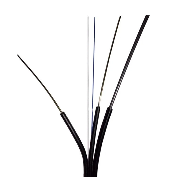
A novel method for aligning multi-core fibers (MCF) provides a systematic approach for MCF splicing in the lab, in cable factories, and in the field. Splicing fiber optic cable is an extremely important phase for making dependable, high-speed communication infrastructures. Regardless of the type of fiber network you're deploying, be it for telecom, enterprise data centers, or smart city infrastructure, fusion splicing provides the benefits of. This is where fiber optic cable splicing—the process of creating a permanent, high-performance join between two fiber ends—becomes critical. For network managers and technicians, a poor splice can lead to significant signal degradation, network downtime, and costly troubleshooting. At Turn-Key. W. Zheng, "Automated Alignment and Splicing for Multicore Fibers," in Optical Fiber Communication Conference/National Fiber Optic Engineers Conference 2013, OSA Technical Digest (online) (Optica Publishing Group, 2013), paper OM3I. However, realising its potential depends on one critical process, which is achieving ultra-low-loss fusion splices that maintain performance and. This guide reveals the secrets to fusion splicing with little fluff—just proven, straightforward techniques refined from years of work in the field. The guide provides the complete workflow, covering safety precautions, tool selection, fiber preparation, fusion operation, quality control, and.
[PDF]

A beamsplitter is a common optical component that partially transmits and partially reflects an incident light beam, usually in unequal proportions. In addition to the task of dividing light, beamsplitters can be employed to recombine two separate light beams or images into a single. Beamsplitters are fundamental components in optical engineering, serving to precisely divide a single input beam of light into two distinct output beams. This division allows for the simultaneous analysis or utilization of the light's properties along two separate paths. It is a crucial part of many optical experimental and measurement systems, such as interferometers, also finding widespread application in fibre optic telecommunications. a laser beam) into two (or sometimes more) beams, which may or may not have the same optical power (radiant flux). Different types of beam splitters exist, as described in the. The beam splitter splits and then recombines infrared radiation, while the detector picks up the resulting signal. It's sensitive to both intensity and frequency. Together, they decide just how accurately an instrument captures those unique infrared “fingerprints” from different substances.
[PDF]

PDH called Parallel Data Highway, is a quasi-synchronous transmission technology based on digital transmission. PDH defines multiple multiplexing levels, such as 2Mbps (E1), 8Mbps (E1). This page defines various terms related to the optical domain. It covers SDH, PDH, SONET, DWDM, FTTH, WDM, PDMA, wavelength converters, optical ADMs, EDFAs, and SOAs. Converts optical light from one wavelength to another. Definitions of common terms related to fibre optics, including SDH, PDH. Part I. SDH is a synchronous TDM technology that multiplexes low-order signals into high-order signals. Because the entire network is. PDH (Plesiochronous Digital Hierarchy), is an early digital transmission standard to handle the transport of digital signals over copper and fiber-optic networks. It appeared in the 1980s and developed rapidly. PDH, in the form of traditional point-to-point connection of various media. The term "plesiochronous" refers to the fact that PDH operates with nearly synchronized timing between. The method was developed to replace the plesiochronous digital hierarchy (PDH) system for transporting large amounts of telephone calls and data traffic over the same fiber without the problems of synchronization. SONET and SDH, which are essentially the same, were originally designed to transport.
[PDF]

It consists of 5 buttons. A power button, a button to turn on the VFL, a lambda button to set the wavelendth, a REF button, and a dBm/W button to set the unit of power. First, you check the initial power of a light signal. Then you check its power at the other end of optical. OPM interface: insert the fiber to be tested, test the optical power. REF/dB key: Short press the dB to switch unit, click once nW/dBm/dB to enter the upper clear data, press and hold until REF is displayed on the screen, and set the current optical power as reference value, enter the relative. There are two buttons on this meter. One is the power button, used to turn the meter on/off. At the top, there is a sensor that detects the light beam. The. at -22 (or 25 with tone on)). To do this you. Active Equipment Power Measurement Fiber Continuity Patch Cable Testing Check MM Reference Cables - Dual OWL MM Sources Check MM Reference Cables - WaveSource MM Sources Check SM Reference Cables - Laser OWL SM Sources Check SM Reference Cables - WaveSource SM Sources. Power-off: Press and hold “MODE” key for 2 seconds or more until “OFF” displays on the screen. Note: This instrument will shut down automatically without receiving any operation instruction for 10 minutes. Function selections: It.
[PDF]

In the following tutorial, we will show how to wire 120V single-phase and 240V split-phase circuit breakers and loads inside a residential main panel. The figure below shows a typical breaker panel used for 120V and 240V circuits. Messy distribution boxes are dangerous and very hard to fix. You will learn to build a safe, efficient, and professional electrical system today. Circuit breaker wiring configurations involve organizing main switches, busbars. A breaker box, also known as a circuit breaker panel, is an essential component of any electrical system. It is responsible for distributing electricity throughout a building, ensuring that each circuit receives the proper amount of power. To understand how a breaker box works, it is helpful to. Each circuit is protected by a circuit breaker, a safety device that automatically shuts off power if it detects an overload or a fault. If you're looking to replace an old fuse box replacement or upgrade your home's power capacity, you'll be dealing with the load center or service panel. The distinction between 1P and 2P circuit breakers plays a pivotal role in determining the appropriate protection level for various circuits. When installing or troubleshooting a power distribution system, understanding how to correctly connect the main electrical supply to the control panel is crucial.
[PDF]
This video shows real on-site footage of electrical installation, demonstrating safe and standardized wiring methods used by professionals. more Learn how to wire a distribution box step by step!. Explosion-proof distribution boxes, vital terminal distribution equipment in power systems, play a crucial role in controlling and protecting industrial electricity in hazardous environments. Given their ubiquity, let's delve into the installation and wiring of indoor distribution boxes today. Choose the right box based on environment (indoor/outdoor), load capacity, and durability. Check for proper IP/NEMA ratings and material quality. These panels are commonly installed in areas like detached garages, workshops, basements, or home additions to manage localized electrical loads. Whether you're an electrician or a DIY enthusiast, this guide will help you understand the basics of home electrical distribution. What is Distribution Board? Distribution board. Common NEMA ratings include NEMA 1 (for basic indoor protection) and NEMA 4 (for corrosion resistance). If your distribution box is installed outdoors and exposed to rain and sunlight, you need to select an electrical enclosure with a higher protection level, such as models with IP66 or NEMA 4.
[PDF]
A transimpedance amplifier (TIA) converts an input current into a proportional voltage, typically using an inverting op-amp with a feedback resistor (Rf). TIAs present a low-impedance input for current-output sensors such as photodiodes, preserving linear conversion and bandwidth. TIAs are conceptually simple: a feedback resistor (RF) across an operational amplifier (op amp) converts the current (I) to a voltage (VOUT). A transimpedance amplifier (TIA) converts a current to a voltage and is often used with current-based sensors like photodiodes. It's also a common building block that helps explain the performance and stability limits of many other op-amp circuits. Despite or because of their simple topologies, TIAs pose rigid tradeoffs among their gain, noise, and bandwidth (BW). The fundamental operation relies on an operational.
[PDF]
A grid networks consist of an interconnected grid of circuits, energized from several primary feeders through distribution transformers at multiple locations. Grid networks are typically featured in.
[PDF]
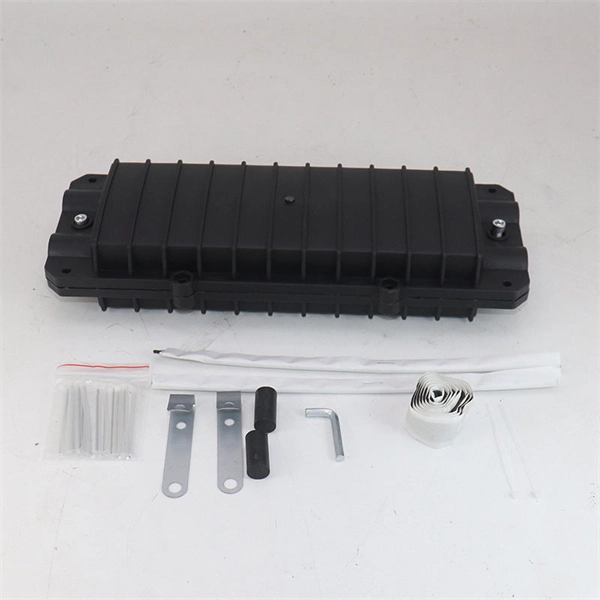
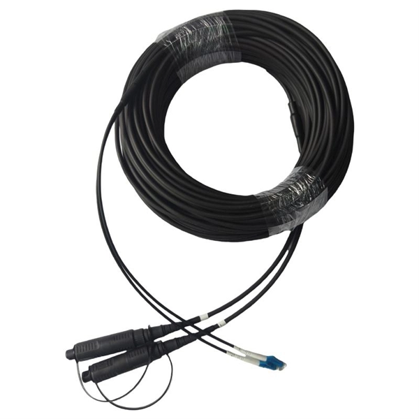
In network cabling, outdoor connections generally use fiber optic cables. When these optical fibers are installed or laid out, a Fiber Termination Box, or FTB, is used to distribute and protect the optical fiber link.
[PDF]

The formula for calculating electrical box size is: . The formula for calculating electrical box size is: . Free electrical load calculation tool for residential and commercial buildings. Calculate service entrance sizing, panel loads, demand factors, and ensure NEC Article 220 compliance. Important: Load calculations must comply with NEC Article 220 and local codes. Always verify calculations with a. How to choose a distribution box of the right size for a project based on load current? If you're like most electrical professionals, picking the right distribution box for your project can feel like navigating a maze. I've been in those shoes - staring at spec sheets, worrying about. The National Electrical Code (NEC) specifies minimum box sizes based on wire gauge and quantity. Proper sizing ensures safety, ease of maintenance, and compliance with regulations. This calculator helps you determine the minimum required box volume based on the number of wires, devices, ground wires, and clamps involved. This ensures compliance with electrical codes and prevents overcrowding. Choose a standard or custom box volume watch capacity update with clear pass or fail status plus tips examples CSV and PDF export for documentation Works for common sizes supports.
[PDF]