Used for hoisting cable trays under I-beams and U-shaped steel. Likely used for specific horizontal support. L-shaped metal profile for support or connection. Various customized brackets made from angle iron. When developing our cable support OBO can offer reliable solutions for systems, three attributes are at the routing and fastening cables securely core of what we do: efficiency, resil- for each of these installation challeng-ience and safety. es in the industrial environment. Our cable support. An electrical cable tray system serves as a rigid structural raceway designed to support and route electrical cables and wires. Unlike a simple wire trough, which is typically a covered channel for shorter runs, cable trays provide a comprehensive support system for complex wiring paths over long. This publication is intended as a practical guide for the proper and safe* installation of cable ladder systems, cable tray systems, channel support systems and associated supports. Cable ladder systems and cable tray systems shall be manufactured in accordance with BS EN 61537, channel support. maintain spacing or to keep cables in place when the tray is ect the minimum bend ra-dius for cables as they exit the bottom of the cable tray. These guidelines are not intended to cover all details or variations in cable ladder and cable tray.
[PDF]
Download new and previously released drivers including support software, bios, utilities, firmware and patches for Intel products. trol I/O is desired. The Q-SYS Core 24f satisfies a broad spectrum of application needs from meeting room environments, conferencing systems, retail establishments, houses of worship, judicial environments, education institutions and other general purpose pro essing applications. A Core 24f may be. That change is why correct leads and connections matter for system stability and lifespan. Please sign in or register for an Intel account. Automatically update your drivers and software Use this tool to identify your products and get driver and. Purpose: This connector serves as the main junction, transmitting essential electrical currents from the supply unit to the motherboard. Design: It features a distinct arrangement of multiple connectors, each designated for specific functions, ensuring balanced and stable power distribution. Product replacement Get replacements and find substitutions for discontinued Schneider Electric products. Where to buy Search our network of verified distributors with over 15,000 sales outlets. Communications bus and supply power terminal blocks, functions, ratings, requirements, and cables provides information about the functions, ratings, and requirements for the communication bus and supply power terminals; and guidelines for wire sizes, cable types, and cable lengths when wiring the.
[PDF]
When encoding diffractive optical elements (DOE) onto a spatial light modulator (SLM), the diffraction efficiency can be reduced because of the pixel nature of the SLM. These effects have been studied previousl.
[PDF]

To properly remove the optical cable: Locate the port > Stabilize the device > Gently grasp & pull the plug (not the cable) straight out > Do the same with the other end > Cover both connectors with plastic tips. To remove the plastic tip: Gently twist and pull off the protective plastic tip from. How To Unplug Optical Audio Cable | How To Remove Optical Cable. For inquiries: tutorialswithterry@gmail. more Sound or visuals were significantly edited or digitally generated. For. Understanding how to remove optical cable is crucial for maintaining the integrity of your audio setup and ensuring a seamless transition between devices. In this guide, we will navigate the intricacies of safely detaching optical cables from various connectors, exploring the proper techniques and. If you have an audio system setup using optical cables, you can easily remove the cables should the need arise for repairs, improvements or replacement. Turn around the first device from which you want to disconnect the optical cable. You should try to get as much access to the cable as possible. In this article, we have provided a step-by-step guide on how to remove a digital optical cable from a TV and also have included some additional tips that you must follow while removing the cable from your TV. So, what are you waiting for? Let's read and remove the cable. Why Does Correctly Remove.
[PDF]
Cable Management Tray Size: Choose a tray size that will hold the desired amount and length of cable. Support Spacing: Remember the NEC requires no more than 4 feet of support spacing. Bend Radius: The tray cable bend radius should be supported to avoid damaging the cable. Hubbell's NEXTFRAME® Ladder Tray is the effective and widely used cable runway that supports and delivers bundles of cable between cabinets, racks, and closets, along walls, and suspended from ceilings. The Ladder Tray features light, rugged, tubular steel construction. It is designed for. maintain spacing or to keep cables in place when the tray is ect the minimum bend ra-dius for cables as they exit the bottom of the cable tray. Proper installation can significantly reduce electromagnetic interference, prevent fire hazards, and improve overall efficiency. This article provides an in-depth. This publication is intended as a practical guide for the proper and safe* installation of cable ladder systems, cable tray systems, channel support systems and associated supports. Cable ladder systems and cable tray systems shall be manufactured in accordance with BS EN 61537, channel support. Is your cable tray system optimized for safety, dependability, space and cost savings? Cable tray (or cable ladder) systems are a popular alternative to electrical conduit systems, as they have an outstanding record for dependable service, design flexibility and cost savings in commercial and.
[PDF]
This guide covers the critical steps, from selecting the right electrical cable tray and performing accurate cable fill calculations to managing a safe cable pull through and ensuring all bonding and grounding requirements are met. Article Summary: A compliant cable tray installation requires a thorough understanding of NEC Article 392, proper structural support, and precise installation techniques. But before you lay the first tray or clamp down a single cable, you need a solid plan. This guide breaks down the process step by step. Here is a step-by-step guide on how to install a standard metal cable tray system (e., ladder or perforated type). Before starting, ensure you have. NEMA VE2 addresses cable tray installation and provides information on maintenance and system modification. NEMA VE2 was developed by the NEMA Cable Tray Section, of which MP Husky is a charter member. Ladder Cable Trays Solid side rail protection and system strength with smooth radius fittings and a wide selection of materials and finishes. Maximum strength for long span applications. Welcome to our step-by-step guide on installing cable trays! In this video, we'll explore the different types of cable trays available and provide detailed instructions for their installation. Whether you're an experienced electrician or a DIY enthusiast, this video is perfect for you.
[PDF]
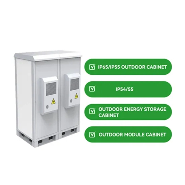
Step-by-step instructions on how to install the Polylok 12" distribution or drainage box. In this guide, we'll break down everything you need to know to install a distribution box correctly and confidently. Choose the right box based on environment (indoor/outdoor), load capacity, and durability. Check for proper IP/NEMA ratings and material quality. Ensure safe placement: install in. The installation of a distribution box is explored in detail, highlighting advanced techniques for achieving a professional and efficient setup. This video provides valuable insights for anyon. more Distribution Box Installation: Advanced Techniques. When it comes to rigid, easy to install electrical box supports, Eaton offers a wide variety of B-Lines series electrical boxes that help reduce installation complexity. For professional installers and property owners, the mechanical components like support rods play a critical role in long-term safety and maintenance efficiency. These components ensure that heavy-duty. Whether you are an electrical contractor or a construction brigade, knowing how to properly and safely install distribution boxes is the basis of ensuring the safe operation of the entire system.
[PDF]