Enable or disable the PoE function on S series switches: 1. system-view. Huawei's comprehensive portfolio of products and solutions enables you to realize smooth digital transformation and rapid growth of virtualization, Big Data, and cloud services. Huawei switches already help customers achieve success in industries such as finance, Internet, retail, education. Welcome to our user-contributed teardowns on the hottest new gadgets. You can write your own teardown, check out how others are contributing with their teardowns, and even check out disassembly photos and comprehensive hardware analysis. Why should I create a teardown? The Lenovo M910s has been. One of them in particular involves the use of Power-over-Ethernet (PoE), but as I don't already have any “standards-complaint” PoE equipment, I needed a cost-effective means of getting a workable set-up. In the early days of 100BASE-TX Ethernet, only two of four pairs of the Ethernet cable were. If one or multiple PoE chips of a PSE are suspended, the port connected to a PD cannot detect the suspension and fails to power the PD. In this case, you can reset the PoE chip. The PoE chip is reset. If PoE power modules are working normally, check whether the PoE card and DIMM are working normally. If the register. Only electrical interfaces of switch models with PWR or PWH in the device names support the PoE function. All views Before using the PoE function, run the display poe device command to check.
[PDF]
PoE switches (Type 1) comply with the IEEE 802. 3af standard, which specifies the maximum power delivered over Ethernet cables. 4 watts of power per port, while PDs can consume up to 12. UPoE supports higher-powered devices, including advanced Wi-Fi 6 APs, video conferencing endpoints, large-screen digital signage, and compact desktop switches. The latest IEEE standard (802. 3bt), supporting up to 90 W per port. UPoE+ can power advanced devices like LED lighting systems. Power over Ethernet (PoE) is a widely used LAN technology that provides DC power to endpoints over existing copper Ethernet cabling used for data connectivity. This eliminates the need for separate power supplies for devices such as IP cameras, VoIP phones, or wireless access points.
[PDF]
Appropriate Ethernet cables must be used to connect with the PoE and normal switch by means of a physical connection. Use the cables correctly and plug each end cable to the corresponding port on each switch to provide stable networking. So, the PoE switch is a networking device through which the PoE passes. In addition, this switch has numerous Ethernet ports that link to network segments, which also help with power and data. Can I use a PoE switch as a regular switch? (Answered) A POE switch gives power to devices that support the protocol, like cameras and access points. A regular switch, on the other hand, merely supplies the internet signal. A regular. A PoE switch simplifies network installation by providing power and data transmission over a single Ethernet cable. However, to take full advantage of a PoE switch, it's crucial to understand how to use it properly. This eliminates the need for separate power adapters, reducing cable clutter and. Just reuse teh POW cables that are alredy up there, and instead of them connecting to POE Wifi adapters, connect them to a POE switch (which would also allow me to add more cameras later) and drop a line from that switch into the main switch in the house. In this article we will uncover the subject matter of PoE switches and watch how they are necessary for the network design.
[PDF]
Shop Upgraded 10 Port 10 100mbps Poe Switch With 8 Port at best prices at Desertcart Honduras. ✓FREE Delivery Across Honduras. ✓EASY Returns & Exchange. FS 100G Switches offer high programmability and scalability, designed for large enterprises and hyper-converged infrastructure (HCI) networks. Learn more!. EXTENDED RANGE - Enjoy data transmission up to 250m, ensuring your devices stay connected even at a distance. ENHANCED SECURITY - One-Key VLAN isolates ports for optimized bandwidth and improved network security. ROBUST COMPATIBILITY - Supports IEEE 802. 3af/at standards, delivering up to 30W per. FS offers PoE+/PoE+ Switches with 1G/2. Plug and play, quick deployment. Ethernet cables transmit data and power, reducing wiring difficulty.
[PDF]
Follow these steps to connect your WiFi router or modem using the TP-Link TL-POE10R POE Splitter: Plug one end of a Cat6 Ethernet cable into a POE port on the POE switch. This cable will carry both data and power. Connect the other end to the Ethernet input port of the TP-Link POE. We can use TL-POE150S and TL-POE10R to expand the network for the place where power line can not reach or there is no outlet. In the topology shown as above, both TL-POE10R and the device which connect to it do not need external power adapter, the TL-POE150S can provide power supply and data for. In this video, we dive into how to use the TP-Link TL-POE10R POE Splitter to supply power and LAN connectivity to a WiFi router, modem, or access point from a CCTV system POE switch. This powerful device simplifies your network setup by delivering both power and data through a single Ethernet. Connecting TP-Link cameras to a POE switch is a seamless, plug-and-play process that powers and networks your security system in minutes. Simply link the camera to the POE switch using a single Ethernet cable—handling both data and power—then configure via the TP-Link app for live viewing and. The Injector sends power and data over the Ethernet cable to the Splitter. Then the Splitter separates the data and power back into two cables and delivers them to the remotely located access point or other network device that requires a 5/9/12-volt power input. 2 Features Complies with IEEE.
[PDF]

On this page you will learn what differentiates a PoE enabled switch from a regular LAN switch, when you should use a PoE switch versus a PoE injector and, what exactly is PoE (Power over Ethernet) technology. A PoE switch simplifies network installation by providing power and data transmission over a single Ethernet cable. However, to take full advantage of a PoE switch, it's crucial to understand how to use it properly. In this blog, we will guide you through the key steps to ensure a successful PoE. A PoE (Power over Ethernet) switch is a network switch that delivers both power and data through a single Ethernet cable to connected devices such as IP cameras, VoIP phones, wireless access points, and IoT devices. PoE Switches - what are they, when to use them, what to know about them, and when not to. Written by Don Schultz, trueCABLE Senior Technical Advisor, Fluke Networks Copper/Fiber CCTT, BICSI INST1, INSTC, INSTF Certified You just bought a nice PoE (Power over Ethernet) switch with cameras and access points. You realize you need to buy Ethernet cable to handle this, but you are a bit. Power over Ethernet (PoE) is a widely used LAN technology that provides DC power to endpoints over existing copper Ethernet cabling used for data connectivity. This allows a single cable to provide both a data connection and enough electricity to power networked devices such as wireless access points.
[PDF]
Let us now see the differences between PoE and Non-PoE Switch. We will take some important parameters and list out the differences. Before understanding PoE, let us quickly take a look at a Network Switch. An Ethernet Switch or a Network Switch is a device that has several RJ45 Portsto connect many devices. The switch will transmit data between ports using the destination MAC Address in the Ethernet Frame. If you consider the OSI Model, Switches are Layer 2 or Data Link Layer d. Now that we have seen the differences between PoE and Non-PoE Switch, the question is which one should you buy? Assume your devices are all non-PoE i.e., computers, laptops, and other networking devices with power supply. In this, you are better off with a regular non-PoE Switch. You can save a lot on the switch but in our frank opinion, this is no.
[PDF]
Power over Ethernet (PoE) does not work directly over fiber-optic cables because fiber-optic cables are designed to transmit data using light, and they do not conduct electricity. PoE requires copper cables (such as Cat5e, Cat6, or Cat6a) to deliver both power and data. Power over Ethernet (PoE) is a useful technology in powering remote devices, but as we see with any copper network cable, the challenge lies in the limited distances of UTP cabling. The maximum distance for Power over Ethernet (or any network data transmission) is 100 meters or 328 feet. However, selecting the right PoE switch requires careful consideration of factors such as projected organizational growth and device. In the field of network cabling and device power supply, Power over Ethernet (PoE) technology has become widely adopted due to its ability to transmit both data and power over a single Ethernet cable. In industrial environments, industrial switches are key network devices that are adapted to harsh. IP cameras that are part of a modern surveillance system are deployed using PoE technology that involves the use of copper based network cabling like CAT5e or CAT6 that has a data transmission limit of 100m (328ft). While that is adequate for installations for a home or small business, large scale. They have dual-port choices and are easy to set up. Media converters work well in many places. You do not have to worry about distance.
[PDF]

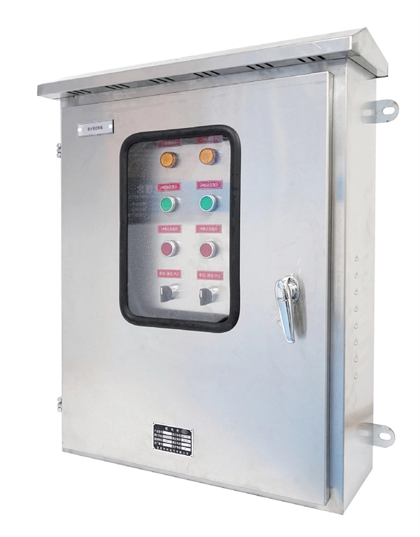
This handbook covers the code of practice in protection circuitry including standard lead and device numbers, mode of connections at terminal strips, colour codes in multicore cables, dos and donts in execution. Also principles of various protective relays and schemes including special protection. Read this document and the documents listed in the additional resources section about installation, configuration, and operation of this equipment before you install, configure, operate, or maintain this product. Users are required to familiarize themselves with installation and wiring instructions. presentation of protection and control relaying. The report will identify methodology behind these practices, present issues raised by the integration of microprocessor relays and the internal logic and external communication configurations, ying. The objective of this presentation is to convey a basic understanding of protective relays to an audience of engineers already familiar with low voltage protective device coordination. HT panel protection relay. The HT power supply is received from GO switch and distributed to the. The handbook for protection engineers includes guidelines on protective circuitry, protective relay principles, and testing procedures for switchgear and relays. It covers standard codes, wiring practices, and norms for protecting generators, transformers, and lines, and provides detailed.
[PDF]

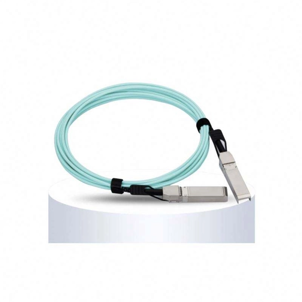
By operating from a single 2. 5V input power rail and integrating the controller, gate driver, power inductor, and MOSFETs, these mini modules are optimized for space-constrained applications like optical modules, wearables, IoT, networking. SFP (Small Form-factor Pluggable) optical modules are compact, hot-pluggable transceivers that enable network equipment to connect seamlessly to fiber and copper links. These modules, including SFP, SFP+, and SFP28, are widely used in enterprise networks, data centers, and carrier-grade deployments. The optical module serves as a crucial component in optical fiber communication systems, operating at the physical layer, which is the lowest layer in the OSI model. Its primary function is to achieve optoelectronic conversion by converting electrical signals into optical signals and vice versa. Think of it as the “translator” for your network equipment, converting electrical signals into optical signals. As an essential component of optical fiber communication, optical modules are optoelectronic devices that facilitate the conversion between optical and electrical signals during the transmission process. They are essential in applications like telecommunications, data centers, and enterprise networks. Optoelectronic devices have transmitting and receiving modes.
[PDF]
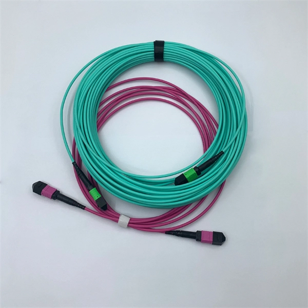
Unlike traditional point-to-point fiber connections, PON systems distribute optical signals from an optical line terminal (OLT) to many optical network units (ONUs) or optical network terminals (ONTs) without requiring active electronic equipment in the distribution network.StatusIn forceYear started2003Latest version(07/10) · July 2010OrganizationOverview G.984 is the series of standards that define the architecture and operation of -per-second–capable (GPON). It is commonly used to implement the link to the customer (the. GPON uses passive optical network (PON) is a access in which a single optical fiber from a central location is shared by multiple end users through one or more in series (cascaded). The standard specifies transmission convergence layer, physical layer requirements, management protocols, and service encapsulation for high-speed fiber access networks. GPON put. In contrast to technology, which deteriorates as the distance between the central office and the household rises, with severe signal loss beyond 3km, all customers may enjoy high-speed network access with.
[PDF]