The PL-1000D simultaneously monitors up to 16 fiber strands, eight on the OTDR and eight on the OSA, and operates standalone over dark fiber, lighted fiber, or a third party network without impacting network traffic. The device monitors the entire D. The PL-1000D simultaneously monitors up to 16 fiber strands, eight on the OTDR and eight on the OSA, and operates standalone over dark fiber, lighted fiber, or a third party network without impacting network traffic. The device monitors the entire DWDM C-band spectrum and provides the optical spectrum, OSNR, and OTDR measurements of the fiber. The OTDR locates fiber cut by sending high powered optical pulses into the fiber and creating Rayleigh back-reflections. The returning signals are measured and calculated, indicating the accurate location and intensity of the fault. The OTDR supports GIS (Geographic Information System) using Rest API, enabling precise geographic location of disrupt. The OSA enables the user to monitor the OSNR and optical spectrum of each fiber and shows a full, accurate and detailed picture of the wavelengths used in the fiber. OSADiagram Graphical Display of the OSA, from PacketLight's LightWatch NMS Please contact usfor a quote or further assistance.
[PDF]

An optical transceiver module, often simply called an optical module, acts as a signal conversion interface in fiber optic networks. It transforms high volumes of electrical signals into optical signals for transmission over fiber cables, or reverses the process at the receiving. In the world of fiber optic communications, optical transceiver modules play a pivotal role as interfaces that convert electrical signals to optical signals and vice versa. If you're dealing with data centers, telecommunications, or AI networking, grasping the key parameters of an optical. Optical transceivers are efficient in changing signals. These modules have many parts, each with a specific functions: Takes in electrical signals to change them. Powers lasers or LEDs to send light signals. Combines many light signals into one for. An optical transceiver, a crucial device utilized in optical communication, is an optoelectronic element, allowing the interconversion of optical and electrical signals during the information transmission. Acting as the "heart" of fiber-optic networks, these modules—ranging. This comprehensive guide breaks down the internal structure, core components (TOSA, ROSA, lasers), and operational mechanisms of SFP optical modules, enriched with technical insights and real-world applications.
[PDF]
Mouser offers inventory, pricing, & datasheets for LC Adapter Fiber Optic Connectors. Corning's extensive line of of LC (lucent connector) connectors offer great performance with very high repeatability and low insertion loss. These products are fully intermateable with standard LC licensed products and deliver long-term stability under a broad range of applications and conditions. 5 mm ferrule connectors without sacrificing performance. LC connectors are available in industry-standard beige (multi-mode), blue (single-mode), and green (angle polish) colors, and will accommodate 900 µm buffered fiber, 1. 6 mm, 2 mm. Search the world's information, including webpages, images, videos and more. Google has many special features to help you find exactly what you're looking for. The name WYSIWYGTM is a trademark of CAST Lighting Limited. Microsoft® and Windows® are registered trademarks of Microsoft Corporation in the United States and other countries. HP and Compaq and the names of HP and Compaq products. Fibertronics offers a variety of LC fiber optic adapters. These are also known as LC fiber optic mating sleeves and are available in both single mode and multimode variants with either a zirconia sleeve or bronze sleeve. Hybrid. Fiber Optic Connectors Mini-Com Duplex Keyed/Non-Keyed LC Adapter Module Keyed B-Red Adapter half on User side and No key on Service Side.
[PDF]
A Fiber Channel SFP is an optical transceiver module purpose-built for Fiber Channel (FC) networks, enabling dedicated, high-reliability communication between servers, switches, and storage systems in SAN environments. Fiber Optic Transmitters, Receivers, Transceivers PC, 5-5,5V, FC con. A tariff of 10 % may be applied if shipping to the United States. A tariff of 10 % may be. Fiber Channel technology (Fibre Channel) is a network storage switching technology that can provide long-distance and high bandwidth, and can realize the transmission of large data files between storage, server and client nodes. Although it shares the same physical form factor as Ethernet SFPs, a Fiber. This article provides a concise overview of FC transceivers, focusing on their core features, technical specifications, and main application scenarios to help professionals quickly grasp this essential technology and optimize storage network deployment and maintenance. With support for Fast Ethernet, Gigabit Ethernet, Fibre Channel and legacy protocols such as SDH/SONET and BiDi, SFP. Fibre Channel (FC) is a high-speed network interconnection technology (usually running at 2Gbps, 4Gbps, 8Gbps, 16Gbps and 32Gbps), which is mainly used to connect computer storage devices. In the past, Fibre Channel was mostly used for supercomputers, but now it is also becoming a common connection.
[PDF]

Optical modules convert electrical signals into light to move data quickly and reliably in AI systems, enabling fast and smooth data processing. Using advanced optical modules boosts AI system speed and bandwidth, helping handle large data loads with low delay and high efficiency. Optical modules. Laboratory utilities: framework for communication with laboratory equipment and post-processing of data (opticomlib. You can install opticomlib using pip: or from source code: NumPy Compatibility: binary_sequence and electrical_signal now fully support NumPy protocols, allowing direct use with. The optical module serves as a crucial component in optical fiber communication systems, operating at the physical layer, which is the lowest layer in the OSI model. Its primary function is to achieve optoelectronic conversion by converting electrical signals into optical signals and vice versa. An. Learn about the components inside a coherent optical engine, what they do, and how they use modulation to send and receive data. Optical communications over metro, long-haul, and submarine networks once used simple direct-detect technology. That's no longer the case.
[PDF]
In modern FTTH architectures, the ODN is the physical fiber layer that distributes optical signals from the central office to end users. Operators consider ODN design as one of the most important factors affecting: Network coverage Optical loss performance Deployment cost. This passive layer is known as the Optical Distribution Network (ODN). Its role is to provide an optical transmission channel between the OLT and the ONU. The ODN network design is a physical facility that connects the communication room and user equipment, and is a key component. Short summary: The Optical Distribution Network (ODN) is the passive infrastructure linking the central office to the subscriber in FTTH. This guide delves into essential ODN components like splitters, distribution boxes, and ODFs, showcasing how Hainan ZTO Cable Co. It's the silent, robust highway that delivers blazing-fast Fiber-to-the-Home (FTTH) and 5G services. The maximum permissible optical power attenuation between OLT optical ports to ONT input is 28dB, which is by utilizing the so-called Class B optical network. At the heart of every Fiber-to-the-Home (FTTH) deployment lies the Optical Distribution Network (ODN) — a meticulously engineered passive infrastructure that enables operators to deliver massive bandwidth, low latency, and reliable service to millions of users. The ODN connects the Optical Line.
[PDF]

To set up your router for fiber internet quickly, connect the router to your fiber modem, access the router's settings via a web browser, and input the provided ISP credentials. Make sure to update the firmware, configure Wi-Fi security, and customize your network name for. Q: How do I install my broadband modem and set up my Internet connection? Installing your broadband modem and setting up your Internet connection involves several steps. First, you need to physically connect your modem to your computer using an Ethernet cable or wirelessly through a router. Next. This wikiHow guide will walk you through setting up a Wi-Fi connection in Windows XP and connecting to the internet. We'll also cover the risks so you know what you're getting into. Check for or install a wireless adapter. Enable Wireless Zero Configuration. Right-click the network icon. Why Use Fiber Optic Internet? Before diving into the setup, let's quickly. Setting up a home network on Windows XP can seem like a daunting task for beginners, but with the right guidance, it becomes a straightforward and rewarding endeavor. This beginner's guide is designed to walk you through the easy steps necessary to establish a functional network within your own. This article provides a detailed guide for establishing internet connectivity in Windows XP via dial-up modem, Ethernet, and Wireless connections, including troubleshooting common issues.
[PDF]

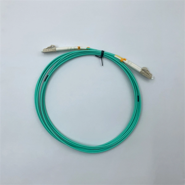
This guide aims to provide a concise understanding of multimode fiber optic cable and its applications. We will explore its characteristics, advantages, specifications, and real-world uses. Multimode fiber (MMF) is an optical fiber designed to carry multiple light propagation paths—or modes—simultaneously. This is made possible by its relatively large core diameter, typically 50 or 62. 5 microns, compared to the ~9-micron core in single-mode fiber. The wider core accepts light from. Multimode fiber optic cables are essential in modern data communication systems since they can transmit data efficiently and at high speeds over short and medium distances. We will explore its. They consist of a transmitter on one end of a fiber and a receiver on the other end. Most systems operate by transmitting in one direction on one fiber and in the reverse direction on another fiber for full duplex operation. Most systems use a "transceiver" which includes both transmission and. Multi-mode optical fiber is a type of optical fiber mostly used for communication over short distances, such as within a building or on a campus. Multi-mode links can be used for data rates up to 800 Gbit/s.
[PDF]

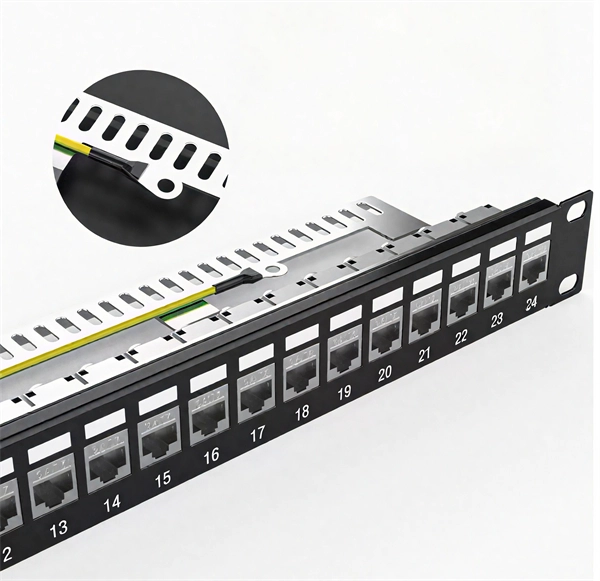
They are the bridge between fiber optic cables in the field and the equipment or patch panels that manage them. By combining factory-installed connectors with spliced bare fiber, pigtails ensure that network installers can create fast, reliable, and cost-effective terminations. Pigtail connections are most frequently used to ground a switch or electrical outlet and for electrical devices that need to connect to multiple circuit wires. A pigtail is composed of three strands of wire. We'll guide you through the fundamentals of creating secure links between multiple conductors and terminals. Pigtails act as bridges, allowing you to connect several wires to a single point without overloading connections. Professionals often prefer this method because it isolates issues. Fiber pigtails are simple in appearance, yet essential in function. It ensures a secure connection by combining wires with a wire connector, like a twist-on connector or a wire nut, and then linking them to the intended terminal or fixture. Pigtails serve. A pigtail wire is a short cable used to lengthen short wires. This pigtail technique is applicable in several home and automotive wiring projects, especially for circuit grounding wires. The National Electrical.
[PDF]

Use the SWD or JTAG interface to connect the ST-Link v2 to the STM32 microcontroller. Download and install STM32CubeIDE or another compatible IDE. Install the ST-Link USB driver (available on the STMicroelectronics. The ST-LINK/V2 is an in-circuit debugger/programmer for the STM8 and STM32 microcontrollers. The single wire interface module (SWIM) and the JTAG/serial wire debugging (SWD) interfaces facilitate communication with any STM8 or STM32 microcontroller operating on an application board. ATOLLIC, IAR and KEIL Integrated Development Environments for. How do you use SWD (Serial Wire Debug) for debugging STM32? - HackMD Using SWD (Serial Wire Debug) for debugging STM32 microcontrollers is a powerful way to monitor and control code execution, inspect registers, and analyze faults. Here's a step-by-step guide to set up and use SWD effectively: 1. In addition. This small guide will explain how to connect your debugger to your development board. There are two commonly used connectors which expose only the SWD (Serial Wire Debug) interface or the full JTAG interface. If you are using one of ST's official Nucleo or Discovery boards, you do not have to. To upload a program to a chip from Thomson Semiconductor you need an ST-Link programmer device to connect your PC. Thompson sells branded programmers, adaptors and cables. We'll use an inexpensive ST-LinkV2. They look like AVR programmers but you need to read the pinouts on the side.
[PDF]
Epson Device Admin is an application that allows you to install devices on the network, and then configure and manage the devices. The following outlines the main features. A complete multi-vendor reference for GPON/EPON OLT configuration, monitoring & troubleshooting. This repository serves as a technical knowledge hub for network engineers working with FTTH (GPON/EPON) infrastructure. It contains configuration commands, troubleshooting methods, power-check commands. Streamline configuration and management for your Epson printer fleet. With automatic device discovery, this intuitive software helps save. OpManager monitors ZTE-ZXPON-EPON-ONU for health and performance. With the help of our ZTE-ZXPON-EPON-ONU device template, you can easily discover and monitor critical performance metrics without any hassle. This guide dives deep into EPON technology, its benefits over alternatives like GPON, and the critical role of optical modules. Whether you're a network engineer or a tech. This document provides examples of configuring Ethernet Passive Optical Network (EPON). The configuration examples in this document were created and verified in a lab environment, and all the devices. Versatile dual-layer tester purpose-built for PON service activation, with added broadband capabilities. The PPM1 leverages a unique patented technology that makes all the difference in the field.
[PDF]

Ensuring Uninterrupted Power Supply: A UPS and DG monitoring system plays a vital role in ensuring uninterrupted power supply. It continuously monitors the power sources, batteries, and overall system performance. A UPS system provides temporary power during electrical outages or disturbances, acting as a bridge until the primary power source is restored or the DG system takes over. They are designed to deliver power instantaneously from energy stored in batteries, super capacitors, or a mechanical storage method. Sensitive electronics, such as computers. UPS or Uninterruptible Power Supply is vital protection against loss of data and costly hardware damage. It ensures that the network systems are operational when the main source of power fails. For home users, a UPS can protect desktop PCs, gaming consoles, and smart home devices from unexpected power cuts. In business settings. These monitoring devices, commonly known as RTUs, will send alerts back to vital personnel via LAN, phone voice message, serial connection, T1, fiber, or other available transport. In this way, organizations can track and log the voltage at the cell level, providing a good assessment of the overall. A 24V DC UPS can manage voltage fluctuations, frequency distortions. These short outages and provide a clean and reliable supply to the control system. With its backup battery pack, a DC UPS designed for an industrial environment will be more resistant to harsh external conditions.
[PDF]
The PL-1000D simultaneously monitors up to 16 fiber strands, eight on the OTDR and eight on the OSA, and operates standalone over dark fiber, lighted fiber, or a third party network without impacting network traffic. The device monitors the entire D. The PL-1000D simultaneously monitors up to 16 fiber strands, eight on the OTDR and eight on the OSA, and operates standalone over dark fiber, lighted fiber, or a third party network without impacting network traffic. The device monitors the entire DWDM C-band spectrum and provides the optical spectrum, OSNR, and OTDR measurements of the fiber. The OTDR locates fiber cut by sending high powered optical pulses into the fiber and creating Rayleigh back-reflections. The returning signals are measured and calculated, indicating the accurate location and intensity of the fault. The OTDR supports GIS (Geographic Information System) using Rest API, enabling precise geographic location of disrupt. The OSA enables the user to monitor the OSNR and optical spectrum of each fiber and shows a full, accurate and detailed picture of the wavelengths used in the fiber. OSADiagram Graphical Display of the OSA, from PacketLight's LightWatch NMS Please contact usfor a quote or further assistance.
[PDF]