BBU end can be connected to CWDM coarse wavelength division multiplexer through CWDM color optical module and OS2 single mode optical fiber patch cord, and then transmitted to CWDM coarse wavelength division multiplexer with one or two optical fibers. The operation of base stations requires a large number of optical modules for interconnection between devices, and we will talk about the application of optical modules in mobile communication base stations. Communication base station is composed of machine room, base station, antenna, feeder. The base station can be divided into two modules: the RRU for transmitting signals and the BBU for processing signals. The BBU is small and exquisite, with low power consumption, while the RRU is large and has high power consumption. In 4G networks, the optical modules used to connect BBU and RRU are mainly gigabit to 10Gbit optical modules. In modern server racks, the wrong optical choice can silently tax performance: queues grow, link training becomes flaky, and operators end up swapping modules mid-quarter. In 5G networks, CPRI is also upgraded to eCPRI. Currently, 5G of the bearer network mainly uses 25Gbps optical.
[PDF]
Identify the Pins: Ensure you correctly identify the live (L) and neutral (N) pins. Connect to Power Source: Insert the 2 pin plug into a compatible power outlet. The 2 pin connector is one of the most versatile and simple connectors. It can be used for a variety of different applications. These small, yet powerful components are found in nearly every device--from smartphones to industrial machinery--connecting electrical circuits and ensuring the smooth. A 2-pin DC power connector offers a compact and efficient solution. In this guide, you'll learn exactly what these connectors are, where they're used, and how to choose the best one for your application. It is commonly found in household appliances and electronics. Neutral Pin – Completes the circuit by returning the current. Since there is no earth pin, these plugs are suitable only for devices with double. The cold-pressed wiring of electrical heavy-duty connectors mainly includes the following steps: 1. Prepare tools and materials: You need to prepare cold-pressed terminals, wire strippers, wire crimping pliers, screwdrivers and other tools and materials. I go over all the components and steps to put together a 2 pin Deutsch connection.
[PDF]

The LS-SM3101-20C SFP transceivers are high performance, cost effective modules supporting data rate of 125Mbps/155Mbps and 20km transmission distance with SMF. The transceiver consists of three sections: a Cooled EML laser transmitter, a APD photodiode integrated with a trans-impedance preamplifier (TIA). The AFCT-5745NPZ/UPZ Lead-free Singlemode Optical Transceivers have been qualified in accordance to the requirement of Telcordia Document GR-468-CORE under the supervision of Avago Technologies Quality & Reliabil-ity Department. This report summarizes the qualification tests over a range of. Copyright © 2022 GOC-UZ. See our terms of use and privacy policy. Volza's Solution gives you 100x return in Six Months! Use strategic filters to explore Optical transceiver module Import data like a seasoned analyst, uncovering hidden opportunities in the Optical transceiver module import business. Our database includes 321 Import shipments, involving 63 Buyers. Up to now, MEISU has developed various high-temperature resistant optical devices not only with regular SM fiber, but also with PM fiber array by applying special high-temperature coating to the normal PM fiber, providing muiltiple choices for silicon photonic (SiPh) solder reflowable assembly at.
[PDF]
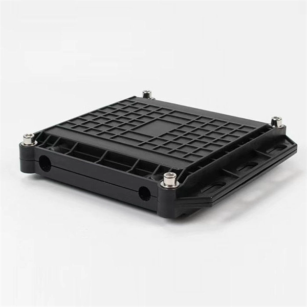
Learn how to install a fiber optic termination box step-by-step for FTTH projects. Covers mounting, splicing, routing, labeling, and testing for indoor/outdoor use. Installing a fiber optic termination box is one of those jobs that looks simple on paper, but it's easy to do poorly in the field. A. A fiber termination box is the standard instrument used in fiber optic networks to connect, secure, and protect optical fibers at the terminating point. It functions as a junction between the incoming fiber cable and the outgoing customer-side fiber cable, where one fiber can be spliced, patched. FTTP or fiber To The Premises applications have reinforced the importance of reliable and stable fiber optic terminations. They also feature resistance to moisture, impact, chemical exposure. A common question we receive is: How do you use a fiber-optic termination box? We recommend using a termination box if you're ordering an assembly with more than two strands. It helps keep your connectors free from contamination and dust, while also keeping your assembly neat and organized. It serves as a termination point for optical fibers, providing a secure and organized space for connecting and managing fiber optic cables. The following steps provide a detailed installation guide for fiber termination boxes: Before starting the installation, you will need the.
[PDF]

This comprehensive guide breaks down the internal structure, core components (TOSA, ROSA, lasers), and operational mechanisms of SFP optical modules, enriched with technical insights and real-world applications. Optical Modules (also known as Optical Transceivers) are critical components in fiber optic communication systems. As the core optoelectronic devices operating at the Physical Layer of the OSI model, their primary function is to perform electro-optical and photo-electric conversion during signal. In the era of 5G, AI, and high-speed data centers, optical modules serve as the core bridge for converting electrical signals to optical signals (and vice versa), enabling fast, reliable data transmission across networks. They are used in fiber optic communication systems to transmit data over long distances with minimal loss and interference. This article systematically identifies common anomalies during optical module installation. Combining hardware principles with practical experience, it. When the industry speaks of optical modules, it refers specifically to small, hot-swappable packaged optical modules, which are used on equipment ports and can be hot-swapped during operation, and are mainly used to convert the electrical signals in equipment (usually switches or router equipment).
[PDF]

Testing solar panels is easy with a multimeter! To test the current, simply connect the multimeter to the panel's output. Set it to read DC current. A multimeter is an indispensable tool for anyone working with solar panels, allowing for accurate measurements and diagnostics. It empowers users to assess the performance, identify faults, and ensure optimal energy production. Without proper testing and maintenance, solar panels can suffer from. In this article, you will learn the step-by-step process of testing your solar panels using a multimeter. We will cover the essential tools you need, the specific measurements to take, and how to interpret the results. By the end of this guide, you will be equipped with the knowledge to diagnose. With just a simple tool—a multimeter —you can quickly measure your panel's voltage and current. This helps you spot issues early and keep your system running efficiently. Connect the multimeter. 🔋 Learn how to test solar panels using a multimeter — step-by-step! I'll show you how to safely check voltage, amperage, and open-circuit power, so you can confirm if your panels are producing the watts you expect. Perfect for DIY solar builders, RV owners, o. We'll also introduce the Honeytek HK78G 2000V PV Multimeter, a professional tool designed for solar testing. Honeytek, a global.
[PDF]

GOOD WILL INSTRUMENT (SUZHOU) CO. Browse online or download User Manual for Equipment Gw-instek GOS-652G. GW Instek GOS-652G User Manual 50MHz Cursor Readout With Delayed Sweep.. GOS-658G 20MHz Cursor Readout... GOS-652G 35MHz. Caution statements identify conditions or practices that could result in damage to this product or other property. THIS APPLIANCE MUST BE the letter E or by the earth symbol or coloured Green or Green & Yellow. EARTHED The wire which is coloured Blue must be connected to the terminal which is. y have a fraction of the total loss compared to fiber-based equivalents. FBG also provides a latency in the o der of nanoseconds as compared to microseconds in fiber-based solutions. The FBG based DCMs are designed to perfectly mimi the dispersion and dispersion slope characteristic of G. 652 fiber. g sensitivity and low water-peak level. Together they allow unlimited use of the whole telecom wavelength win ow for a great variety of applications.. GOS-653G Basic... GOS-622G. The GOS-653G/652G Series is an example of classic analog oscilloscope design. The GOS-653G /652G cover a broad range of industry applications, such as product design, assembly lines, repair & servicing, and educational purposes for EE laboratories and class experiments. Coupled with various trigger.
[PDF]
Mouser offers inventory, pricing, & datasheets for LC Adapter Fiber Optic Connectors. Corning's extensive line of of LC (lucent connector) connectors offer great performance with very high repeatability and low insertion loss. These products are fully intermateable with standard LC licensed products and deliver long-term stability under a broad range of applications and conditions. 5 mm ferrule connectors without sacrificing performance. LC connectors are available in industry-standard beige (multi-mode), blue (single-mode), and green (angle polish) colors, and will accommodate 900 µm buffered fiber, 1. 6 mm, 2 mm. Search the world's information, including webpages, images, videos and more. Google has many special features to help you find exactly what you're looking for. The name WYSIWYGTM is a trademark of CAST Lighting Limited. Microsoft® and Windows® are registered trademarks of Microsoft Corporation in the United States and other countries. HP and Compaq and the names of HP and Compaq products. Fibertronics offers a variety of LC fiber optic adapters. These are also known as LC fiber optic mating sleeves and are available in both single mode and multimode variants with either a zirconia sleeve or bronze sleeve. Hybrid. Fiber Optic Connectors Mini-Com Duplex Keyed/Non-Keyed LC Adapter Module Keyed B-Red Adapter half on User side and No key on Service Side.
[PDF]
Double jacket fiber optic cable is usually the right choice when a route faces outdoor exposure, building-entry transition, direct-burial risk, rodent pressure, or higher mechanical abuse than a standard indoor cable can handle comfortably. Outdoor fiber optic cable plays a critical role in connecting buildings, deploying security and access control electronics, extending networks across campuses, supporting broadband deployments and enabling reliable communication in harsh environments. The key is that “double jacket” is not a universal premium. Fiber optic cables are the backbone of modern communication systems, offering exceptional speed, bandwidth, and resistance to electromagnetic interference. Designed to survive decades of UV exposure, temperature swings, moisture, mechanical stress, and rodent attacks, these. Fiber optic cables are specialized cables that use light to transmit data at incredibly high speeds. Unlike traditional copper cables, fiber optics is immune to electromagnetic interference, offers higher bandwidth, and allows for more reliable, long-distance connections. These cables are widely. Plan your outdoor fiber installation carefully by surveying the site, choosing the right cable type, and following FOA and OSP standards to ensure reliability. Select the best installation method—direct burial, aerial, conduit, or underwater—based on your environment and future network needs.
[PDF]

In this beginner-friendly guide, we'll explain what it is, why the “APC” matters, the different types you can buy, how to select the right model, and how to install and test it correctly. What is an SC/APC Fiber Optic Adapter?. Fiber optic adapters, also known as couplers, play a crucial role in fiber optic networks by providing a connection point between two fiber optic connectors. They enable seamless and reliable optical signal transmission between different fiber optic cables, connectors, or devices. Using the wrong type or neglecting cleaning can lead to signal loss and unstable connections. This guide covers adapter types, selection criteria, cleaning tips, FAQs, and B2B customization options to help businesses build reliable and scalable fiber networks. It ensures precise alignment between fibers and facilitates effective transmission of optical signals. Without the proper adapter, signals can degrade or become unstable, which can dramatically decrease the reliability of a network.
[PDF]

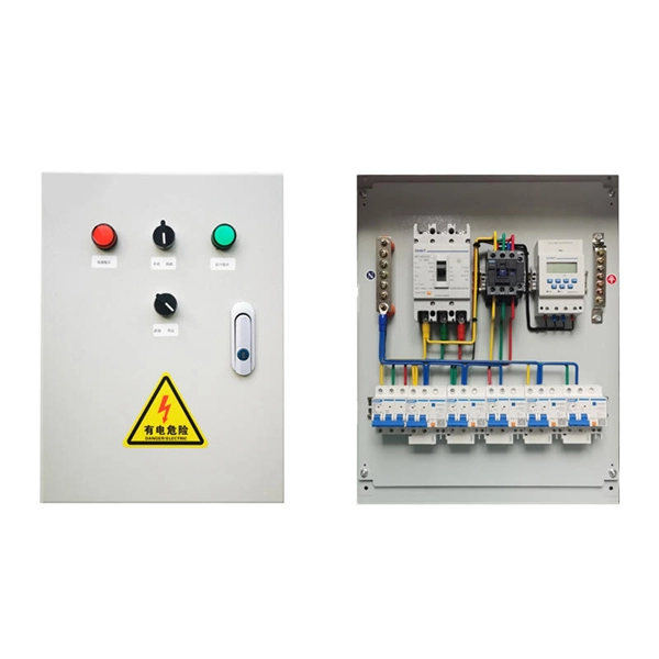
The distribution box is a crucial piece of equipment that connects solar panels to the AC power grid. Solar energy is a clean, renewable, and pollution-free source. A Solar Distribution Box plays a critical role in managing, controlling, and distributing electrical power safely within solar systems. Without it, the risk of electrical faults, system failures, and energy loss increases significantly. As solar adoption continues to rise globally, understanding. A panel junction box is typically mounted on the back of a solar module. It serves as the module's protected connection point—housing internal electrical terminations and enabling safe, standardized external connections via connectors. A PV combiner box is installed at the system level. Its primary. In modern solar PV installations, multiple strings of solar panels generate direct current (DC) power that must be safely consolidated, routed, and protected before it reaches the inverter. Handling high-voltage DC electricity requires precision and uncompromised safety measures. This essential device incorporates sophisticated protection mechanisms and monitoring capabilities to ensure.
[PDF]
Power over Ethernet (PoE) does not work directly over fiber-optic cables because fiber-optic cables are designed to transmit data using light, and they do not conduct electricity. PoE requires copper cables (such as Cat5e, Cat6, or Cat6a) to deliver both power and data. Power over Ethernet (PoE) is a useful technology in powering remote devices, but as we see with any copper network cable, the challenge lies in the limited distances of UTP cabling. The maximum distance for Power over Ethernet (or any network data transmission) is 100 meters or 328 feet. However, selecting the right PoE switch requires careful consideration of factors such as projected organizational growth and device. In the field of network cabling and device power supply, Power over Ethernet (PoE) technology has become widely adopted due to its ability to transmit both data and power over a single Ethernet cable. In industrial environments, industrial switches are key network devices that are adapted to harsh. IP cameras that are part of a modern surveillance system are deployed using PoE technology that involves the use of copper based network cabling like CAT5e or CAT6 that has a data transmission limit of 100m (328ft). While that is adequate for installations for a home or small business, large scale. They have dual-port choices and are easy to set up. Media converters work well in many places. You do not have to worry about distance.
[PDF]

Connecting a multi-mode SFP to single-mode fiber creates a major signal mismatch. A small portion of the transmitted light gets captured. This leads to high attenuation and frequent link drops. I suggest you avoid such setups. Use them if essential and with proper mode. A Fiber Channel SFP is a specialized optical transceiver designed exclusively for Fiber Channel (FC) networks, enabling high-speed, low-latency, and lossless data transmission in Storage Area Network (SAN) environments. These transceivers comply with the ANSI INCITS 404-2005 Fiber Channel standard and IEEE 802. 3 for. There are two main types of fiber optic cables: single mode and multimode. Although they can do the same job in some instances, the different construction methods make each of them better suited to certain tasks and budgets. That makes picking between single mode and multimode fiber optic cables an. Single-mode (SMF) and multi-mode fiber (MMF) use different core sizes, sources and wavelengths. Understanding the compatibility constraints prevents costly downtime and troubleshooting. What Is the Difference Between Single Mode and Multimode Fiber? The main difference between these fiber options comes down to how light travels through. What is Single-mode SFP? Before we compare them, we need to know their brief definitions. A single-mode SFP is specially used with the 9/125µm single-mode fiber (SMF) but can not be used with multimode fiber cable.
[PDF]
Picking up the best router for fiber internet isn't just about going to the market and choosing one of the best wireless routers. Instead, you need to carefully look at its specs, performance, and the type of securit.
[PDF]
Used for hoisting cable trays under I-beams and U-shaped steel. Likely used for specific horizontal support. L-shaped metal profile for support or connection. Various customized brackets made from angle iron. When developing our cable support OBO can offer reliable solutions for systems, three attributes are at the routing and fastening cables securely core of what we do: efficiency, resil- for each of these installation challeng-ience and safety. es in the industrial environment. Our cable support. An electrical cable tray system serves as a rigid structural raceway designed to support and route electrical cables and wires. Unlike a simple wire trough, which is typically a covered channel for shorter runs, cable trays provide a comprehensive support system for complex wiring paths over long. This publication is intended as a practical guide for the proper and safe* installation of cable ladder systems, cable tray systems, channel support systems and associated supports. Cable ladder systems and cable tray systems shall be manufactured in accordance with BS EN 61537, channel support. maintain spacing or to keep cables in place when the tray is ect the minimum bend ra-dius for cables as they exit the bottom of the cable tray. These guidelines are not intended to cover all details or variations in cable ladder and cable tray.
[PDF]