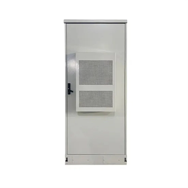
This section provides an overview for server racks as well as their applications and principles. Are you choosing the right server rack manufacturer for your business? Whether you need racks, wall mounted network cabinets, or server cabinets, there are a variety of options available in the United States. Here are the top-ranked server rack companies as of April, 2026: 1. Cyber Power Systems USA. Some of the features include one-piece hinged covers, adjustable vented shelves, vertical cable management, floor mounting holes, integral front waterfall tops, pre-drilled holes, heavy gauge steel frames and vertical mounting-hole patterns. more+ Indoff is estimated to have 200-499 employees. At Rackmount Solutions, we provide rack, cabinet, and physical infrastructure systems designed with safety, protection and adaptability in mind. From open-frame racks to fully enclosed cabinets, our solutions keep equipment secure, organized, and ready for growth. We believe connectivity is the. Discover leading server cabinet manufacturers in the USA: Eabel, Hubbell, and others. Innovative, custom IT infrastructure solutions for diverse needs. They help to organize and secure important equipment by housing them. By selecting a reliable server cabinet manufacturer, you can make sure your equipment gets the best performance which is needed for data centers, networks and IT.
[PDF]
Reference for all Rack-level parameters that configure Convox infrastructure, networking, scaling, and security on AWS. This document outlines recommended best practices when bidding for server capacity. Understand You Pay the Market Price, Not Your Bid This is the most crucial concept: Your Maximum Bid Price is just a ceiling. You are only charged the current, lower Market Price for the instance type as long as. This page contains documentation on the specific parameters required by each supported bidder. These docs only apply to Prebid Server-based bidders. For each bidder listed below, you'll find the following information: A table of features supported by. Rack parameters are configuration settings that control various aspects of your Convox rack. These parameters allow you to customize and optimize the behavior of your applications and services running on the rack. When installing a new rack through the Convox Console, you can configure parameters. If spot instances are available for the bid price, the Rack instances will use spot instances instead of on-demand instances, resulting in significant cost savings. If the parameter is empty, spot instances will not be utilized. Only HTTPS, SSH and the local console port are enabled. Some interfaces require creation of associated authentication credentials before they can be enabled. DHCP Configuration The Default boot mode is DHCP only.
[PDF]
A small server rack should provide long-term value by balancing affordability with durability and functionality. Consider both the initial cost and the long-term benefits when selecting a network rack enclosure. By the end of the week, that blank space held a fully functional network core designed to keep a small professional office online through power cuts, ISP hiccups, and future growth. If you run a home office or manage IT for a small office or business, this summary shows the workflow and gear that. Whether supporting a handful of network switches in a small office or housing rows of servers in a bustling data center, the right network rack protects, organizes, and sustains the technology that drives your business forward. This in-depth guide will give you a 360-degree view of the. Wall-mounted server racks are specifically designed to house network equipment, patch panels, routers, and compact servers in vertical enclosures that mount securely to the wall.
[PDF]
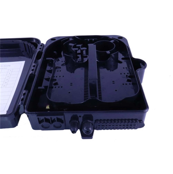
ODF, also known as optical distribution frame or fiber optic patch panel, is a critical device used in optical communication for managing and distributing optical fibers. It is usually a compact and structured framework composed of a steel shell and internal fiber splice tray as the. This complete guide explores everything you need to know about ODFs — from their structure, types, and key components, to installation best practices and modern design trends. Whether you're building a central office, data center, or FTTx distribution network, understanding the right ODF. An Optical Distribution Frame (ODF) is the central hub for fiber splicing, termination, patching, and cable protection in modern optical networks. Mainly used in the junction point between the optical transport networks and the optical transmission equipment, or bet een the optical fiber access networks and the user cable. It serves as a merging point for the optical fibers, where connections are consolidated and routed, thus minimizing signal attenuation. The ODF includes.
[PDF]

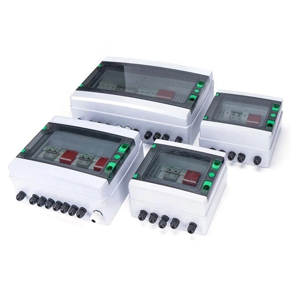
Follow a step-by-step process: mark the location, drill holes, insert anchors, and secure the box for a weatherproof fit. Apply weatherproof sealant around the box edges and cable entry points to prevent water ingress. Installing an electrical box on an exterior wall can seem daunting, but with the right guidance, it can be a straightforward task. Whether you are adding an outdoor outlet for convenience or setting up lighting, understanding the process is key. This guide will walk you through the essentials of. An electrical junction box is a protective housing designed to enclose and shield electrical wire connections or splices. For outdoor installations, the box must defend these sensitive splices against moisture, dust, temperature fluctuations, and physical impacts. Safety remains crucial during installation. It takes the incoming power and safely distributes it to different circuits throughout your building. Whether in a home or an industrial facility, this box keeps your electrical setup organized, functional, and efficient. Whether adding a GFCI outlet for safety or upgrading an exterior outlet for weather-resistant durability, it's essential to follow proper electrical wiring. In this video, I'll show you how to install a weatherproof outdoor electrical box — safe, secure, and code-compliant.
[PDF]
Encuentra y compara las mejores soluciones de Rack y Gabinetes de Servidores en Colombia. Selecciona la opción que mejor se ajuste a tus necesidades y solicita cotización al proveedor. Internet providers in Colombia are evolving rapidly, offering faster speeds, wider coverage, and competitive pricing across the country. Whether you're in a major city or a growing town, finding the right ISP can transform how you work, stream, and stay connected. This guide explores the top. CoreSite Colocation Services is a service that provides scalable data center solutions designed to facilitate secure and reliable housing of IT infrastructure. The service offers space, power, cooling, and physical security for servers and network equipment, enabling businesses to optimize their.
[PDF]
An Optical Distribution Frame (ODF) is a dedicated unit designed to organize, terminate, and interconnect fiber optic cables. It brings together fiber splicing, patching, and cable routing in a single structure, while shielding sensitive connectors and splices from mechanical. In the complex architecture of fiber optic networks, the Optical Distribution Frame (ODF) serves as the linchpin for organizing, protecting, and distributing optical signals. Whether in data centers, telecom central offices, or enterprise network rooms, ODFs enable efficient fiber management. Among the many solutions available, the Optical Distribution Frame (ODF) plays a central role in organizing, protecting, and simplifying fiber management in telecom rooms, central offices, and data centers. As data centers, enterprises, telecom operators, and smart-building infrastructures deploy increasingly dense fiber links, ODFs provide the structured. Optical Distribution Frames (ODF) are indispensable components in optical communications networks. They provide efficient fiber optic management, connectivity, and protection. Whether you are building a data center, deploying FTTx networks, or managing the telecom systems, the selection of suitable ODF is very important since the fiber connections are optimized.
[PDF]
Please view our full RLH price list and contact us at info@fiberopticlink. com if you have any questions or special project needs. A Fiber Optic Patch Panel, also known as an Optical Distribution Frame (ODF) or fiber termination enclosure, is a centralized hardware unit designed to manage, protect, and organize fiber optic cable connections. In an era where data speeds and network reliability are non-negotiable, the patch. fiber optic patch panel, odf, optical distribution frame, fiber distribution panel, rack mount fiber patch panel, wall mount odf, fiber termination box, 1u fiber patch panel, 24 port fiber patch panel, 48 port fiber patch panel, outdoor fiber patch panel, fiber optic odf, sliding patch panel The. Q1: What is the difference between an ODF and a patch panel? An ODF is the entire frame or cabinet managing fiber connections, while a patch panel is a modular unit inside the ODF for cross-connecting fibers. Q2: How many fibers can an ODF handle? It depends on the ODF type; rack-mount units can. ODF is used in the terminal access link of FTTH system. It is a device that splices, distributes, and splits optical fibers and provides protection and management of optical fibers. Belden offers several Fiber Patching Systems. Full patching platforms include FX ECX for LAN environments, FX UHD for high-density fiber channels and the DCX System used primarily in data centers where high amounts of fiber connections and density are the key requirements, as in optical.
[PDF]
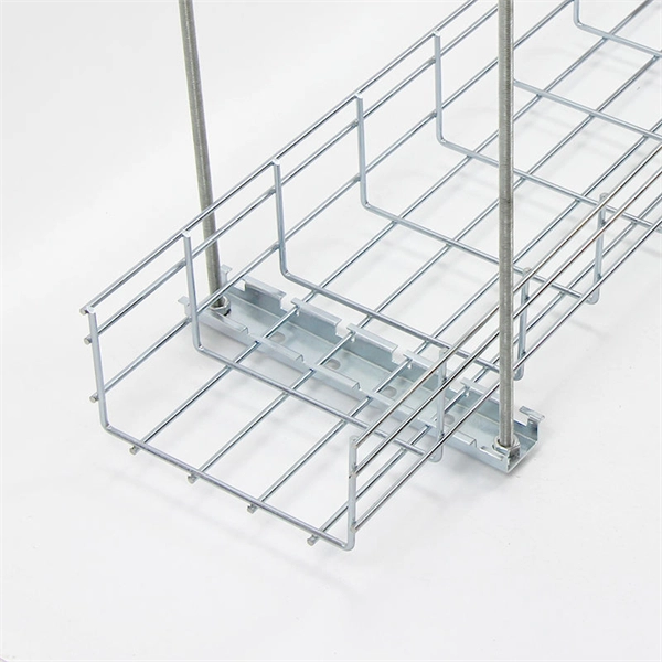
The typical cost of 1U space in a 45U server cabinet is $55. Therefore: Average cable management cost is . Basic cable management systems (cable trays, ties): $200 to $1,000 per rack. Power and Cooling Infrastructure Power Distribution Units (PDUs): $200 to $1,500 per unit, depending on capacity. 73/U The. Durable & Easy to Install: Made from sturdy plastic for long-term use in IT environments. Installs easily on standard rack rails using the included M6 screws-no special tools required Each item has a unique code that we verify before shipping. com Return Policy: Amazon. com. Sysracks offers a wide array of data closet cable management products for different devices: Horizontal managers: Our 1U wire managers are designed to suit any 19” cabinet. This allows structured routing of twisted-pair wires and patch cords and ensures the correct cord radius to prevent twisting. Shop top-quality rack cable managers for efficient data center wiring. Get a horizontal/vertical cable manager to safely organize and protect your cables. Our 1U and 2U cable managers reduce slack, improve airflow, and create clean, serviceable rack layouts designed for scalability.
[PDF]
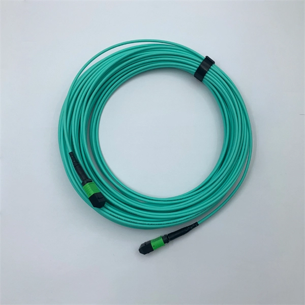
In this blog, we'll walk through the standard procedures for installing racks and assembling MPO systems in modern data centers. Before any hardware is installed, detailed planning is essential. Rack placement must consider airflow, power distribution, cable routing, and physical. Proper installation of components in a data center server rack is crucial for optimal performance, efficient maintenance, and long-term reliability of your IT infrastructure. The term breaks down into two distinct phases: “racking” involves assembling and mounting servers, switches, storage devices, and networking equipment into. Best Practices for Data Center Rack and Stack Installation in 2025. Data centers are the backbone of modern technology, and ensuring their infrastructure is installed correctly can significantly impact performance and scalability. Data. However, before you get down to installation itself, it's necessary to prepare for it. A preparatory stage includes several important pre-installation steps that ensure smooth and durable functioning. These include: Choosing the right rack type. Server furniture differs a lot. Modern manufacturers. Four-Post Racks To mount two-post racks, the equipment has to be bolted to two vertical posts, in most cases at the front. They are simple, cheaper than other types, and occupy less space. They are a good choice for small IT rooms or closets with minimal depth requirements and lightweight devices.
[PDF]
Huawei MA5683T is an aggregation Optical Line Terminal (OLT), it supports up to 6 service slots and can support a maximum of 12,000 subscribers (GPON). MA5683T has GICF/X2CS Uplink Board available for selection, and two power slot redundancy for DC power input. Ethernet link aggregation increases link bandwidth by bundling multiple physical links to form a logical link. Link aggregation can work in manual mode or Link Aggregation Control Protocol (LACP) mode. In manual mode, you must manually create an Eth-Trunk and add member interfaces to the Eth-Trunk. As shown in Figure 1, SwitchA and SwitchB are connected to the networks of VLAN10 and VLAN20, respectively, via Ethernet links, and there is a large amount of data traffic between SwitchA and SwitchB. Link aggregation has the following advantages:. Original operating mode: Two S5700s were configured with Eth-Trunk1, and the ports of the three lines that need to be communicated were added to Eth-Trunk1. Set the port to access to allow the corresponding VLAN to pass; so that the two floors of the network can communicate normally In this way. And there are two link aggregation types. In LACP mode, there are active and backup links and backup links are used for redundancy. For this example, we. Link Aggregation is a technology defined in IEEE 802. It enhances bandwidth, provides fault tolerance, and allows load balancing between connected devices. Key benefits of link aggregation: Higher.
[PDF]

The first thing you should do is locate the fiber optic cable that comes from the service provider. Once inserted, make sure it is securely. However, setting up a fiber optic connection to your router can seem daunting if you're unfamiliar with the process. Why Use Fiber Optic Internet? Before diving into the setup, let's quickly. Ensure your fiber optic router has an available WAN (Wide Area Network) or Ethernet port for the fiber optic modem. It's thin, flexible, and usually comes with connectors on both ends. Power Cables: Get power cables for both the. The fiber optic cable does not plug directly into a standard home router because the signal type must be translated. The fiber line terminates at the Optical Network Terminal (ONT), which is typically supplied and installed by the internet service provider. This specialized equipment serves as the. The process to connect fiber optic cable to router requires careful attention to detail, but I'll walk you through every critical step with the precision and clarity you deserve. Here's a step-by-step guide to help you through it. Understand the Basics Before diving in, familiarize yourself with the components involved:. Follow along as we take you through the step-by-step process of installing fiber internet! From preparing the site to connecting the final cables, we'll show you what goes into bringing high-speed internet to your doorstep. Whether you're a tech enthusiast or just curious about how it all w.
[PDF]

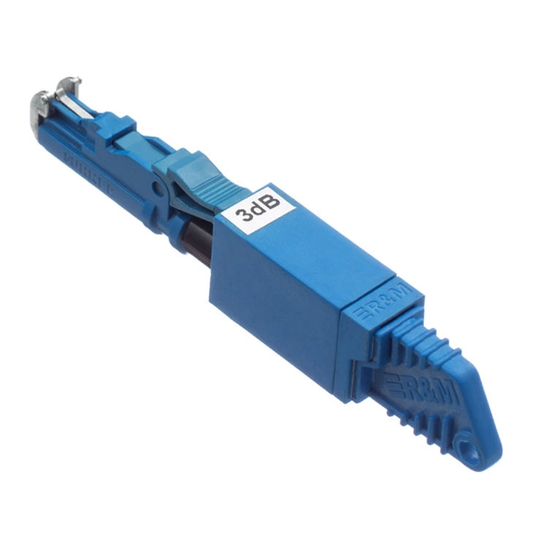
Wavelength: 1310nm, 1550nm, or CWDM/DWDM wavelengths. LR (Long Range): 10km, 1310nm, Blue latch. Each SFP module operates at a specific wavelength, and to avoid confusion, manufacturers use color-coded pull rings for easy identification. Here's a quick guide: 🔹 850nm (Black) – Short-distance multimode fiber (up to 550m) 🔹 1310nm (Blue) – Longer reach, typically used for single-mode fiber (up. Wavelength division multiplexing modules differ from other optical modules in center wavelengths. Wavelength division. Coarse Wavelength Division Multiplexing (CWDM) SFP modules are a practical and cost-effective solution for expanding network capacity while keeping equipment simple and scalable. Selecting the right wavelength for CWDM SFPs is essential to ensure optimal performance, minimal interference, and. Every optical transceiver operates at a specific wavelength, typically measured in nanometers (nm). Their pull. SFP (Small Form-factor Pluggable) is a compact, hot-swappable module used in network devices such as switches, routers, and servers to provide network connectivity and is widely used in network communications. Think of it as the “translator” for your network equipment, converting electrical signals into optical signals.
[PDF]
Locate your ONT/ONU: This is typically a small box provided by your ISP, often located near where the fiber optic cable enters your home. Connect the fiber optic cable: Plug the fiber optic cable from your ISP into the designated port on your ONT/ONU. This is usually clearly labeled. However, setting up a fiber optic connection to your router can seem daunting if you're unfamiliar with the process. In this guide, we'll walk you through how to connect a fiber optic cable to a router safely and efficiently. Why Use Fiber Optic Internet? Before diving into the setup, let's quickly. To set up your router for fiber internet quickly, connect the router to your fiber modem, access the router's settings via a web browser, and input the provided ISP credentials. Make sure to update the firmware, configure Wi-Fi security, and customize your network name for optimal performance. With. Setting up a fiber internet connection requires understanding key hardware components and following a specific connection sequence to establish your home network. Here's a simple guide to help you through the process: 1. Check Your Fiber Optic Equipment Before you start, make sure you have the necessary equipment: Fiber Optic Modem (ONT – Optical Network Terminal):.
[PDF]
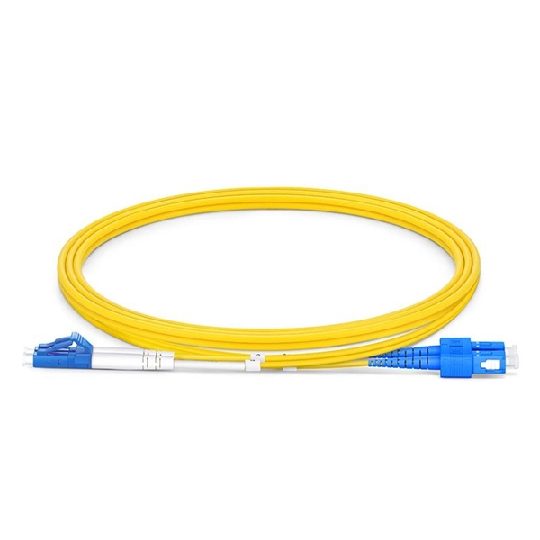
The SFP port is a built-in optical port of a Gigabit Ethernet switch, so it cannot be directly connected with a twisted pair or a jumper. It needs to be connected to an optical module first, and then it can be transmitted with an optical fiber patch cord. This chapter describes how to configure Gigabit Ethernet switching on the Catalyst enterprise LAN switches. Note For complete syntax and. Si ce produit est vendu au Canada, vous pouvez accéder à ce document en français canadien à https://www. com/support/download/. The RJ45 port is for copper cable. al installation guidelines and recommended procedures. To deploy this switch effectively and ensure trouble-free operation it is recommended to first read the relevant sections in this guide so rk administ tors and support personnel that install, e is based h relevant specif tions and. This command is configured in layer-2 interface configuration mode. The optical interface speed is fixed. The optical/electric port cannot support the gigabit and full-duplex at the same time. The ordinary TX port does not. The guidelines for configuring speed on QFX5100-48T switch are as follows: If the speed on the switch is set to 10-Gbps or auto, the switch advertises all the speeds. If you have configured the speed to 100 Mbps.
[PDF]