
This guide provides a complete framework for understanding, identifying, and planning MPO connector gender in data center environments. Visually, male and female MPO connectors are easy to distinguish: male connectors feature two alignment pins (PIN pins), while female connectors have corresponding holes instead of pins. An MPO connection is made between a male and female connector to make sure that there is proper alignment. Interfaces on active MPO equipment, such as transceivers are usually male, so any MPO trunk cable. In modern data centers and high-density fiber optic networks, MPO (Multi-Fiber Push-On) connectors have become an essential solution for achieving fast, reliable, and scalable connectivity. You will discover the physical distinctions between male and female connectors and how to develop a gender strategy for your infrastructure, which gender connects. Whether you're supporting parallel optics like 100G SR4 or densifying an optical distribution frame (ODF), MPO is now a cornerstone of network design. This article explains: And a practical checklist to design MPO systems that scale cleanly. If you only remember one thing: MPO is a multi-fiber. In MPO and MTP fiber connector systems, Male vs Female and Pin vs No-Pin describe the same core engineering attribute: the presence or absence of alignment pins on the MT ferrule. Unlike single-fiber connectors such as LC or SC, this distinction is not optional terminology but a mandatory.
[PDF]
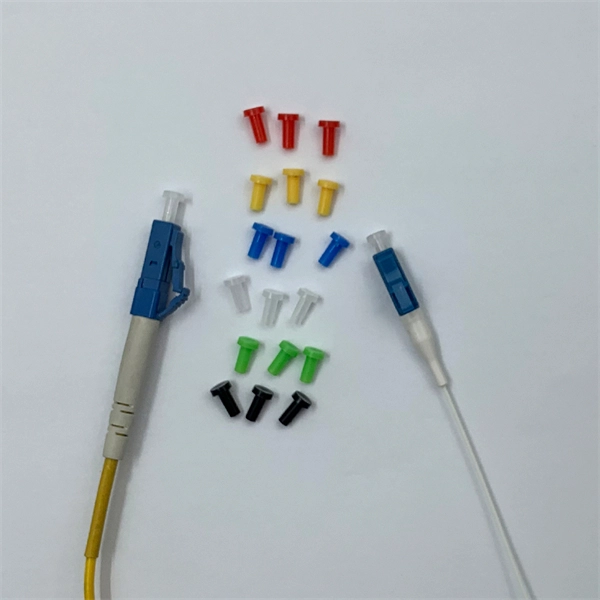
Once you have your modules and fiber in hand, the process is simple: Insert the SFP modules into the SFP or SFP+ port of your UniFi device. Plug in the fiber cable, LC connectors click right into the module. Power on both devices. Watch for a link light, if you see green . LC connectors are quickly becoming the connector of choice due to their compact size and outstanding performance. This guide will walk you through the key steps for properly connecting LC fiber connectors. LC fiber connectors feature a small form factor design that takes up very little space. LC (Lucent Connector) fiber connectors are small form-factor connectors widely used in telecommunications and data center environments. These connectors feature a push-pull coupling mechanism and a 1. 25mm ferrule, making them ideal for high-density applications. Understanding how to properly. By following these steps and precautions, you can ensure a reliable and high-quality connection with LC fiber connectors, enhancing the stability and performance of your network. The abbreviation LC for fiber optic connectors stands for Lucent Connector and literally means “translucent/transparent. The LC connector is about half the size of an SC connector. It meets TIA/EIA-604-10 standards, ensuring compatibility and performance across manufacturers. Learn how to use LC connectors for efficient networks.
[PDF]
* Bronze alloy bolts shall have a minimum tensile strength of 70,000 pounds per square inch. ** Bolts, cap screws, nuts, flat washers, locknuts: 18-8 alloy. Qualified to meet or exceed all the nationally recognized standards, including ANSI C119. 4 and NEMA CC1, the DMC Power system raises the quality, safety and productivity standard. Other aluminum compression connectors are made from com-mercially pure high conductivity wrought aluminum. Select type of connector from those listed below and follow the indicated procedure. ** Belleville Washers: 302 alloy. EX: TPC600-4N4-AA-GS TYPE TPC-N-AA Terminal Connector A C FIG. 3 T Terminal is designed to connect to aluminum or copper pads. Pad conforms to NEMA standards. 56 © 2011, AFL, all rights reserved. PP-3-00479. This publication contains the following new or updated information. This list includes substantive updates only and is not intended to reflect all changes. Added information about using a Top Hat Rail, catalog number 141A-AHR45, with a Adapter Extension Module, catalog number 141C-X40. Examples. We have recently reviewed our company's bus torque chart and found some of the values are in line with the bolt mfg suggestions (i. - 1/2" - 3/4" bolts). I started to update our torque chart to match the.
[PDF]
Pricing (USD) Filter the results in the table by unit price based on your quantity. A tariff of 8% may be applied if shipping to the United States. SHENZHEN FORMAN PRECISION INDUSTRY CO. ZHEJIANG JINGHONG ELECTRIC CO. Bus bar connectors are critical components in electrical power distribution systems, providing secure, low-resistance connections between bus bars and other conductors such as cables and circuit breakers. A. The global bus bar connector market is experiencing steady growth, driven by rising demand in industrial automation, renewable energy, and electric vehicle (EV) manufacturing. According to a 2023 report by Grand View Research, the market size reached $12. 4 billion in 2022 and is projected to grow. In what shapes, busbars are manufactured? Busbars are manufactured in metallic strip, rods and solid bars. The rods can be solid or hollow inside. What are the most suitable metals for busbars? For manufacturing busbars, copper and aluminium are the most preferred metals.
[PDF]

This guide delves into the structure and working principle of fiber optic connectors and outlines the critical steps for creating a successful connection. There are many types of fiber optic connectors, including SC, LC, FC, ST, D4, MU, MT/MPO, etc. These connectors can be divided into single-mode and multi-mode fiber optic connectors according to their structure and purpose. To learn more about the types of fiber optic connectors, click here: Types. Proper connection of fiber optic cables is essential to harness these benefits fully, as even minor errors can lead to significant performance issues like signal loss. This article will guide you through the necessary tools, materials, and methods on how to connect fiber optic cables effectively. At the heart of any robust fiber optic network lies a crucial process: Preparing a fiber cable for termination of a connector or splice. Fiber optic connectors play an essential role in the realm of optical communication, enabling seamless connections between fiber optic cables. We terminate fiber optic cable two ways - with connectors that can mate two fibers to create a temporary joint and/or connect the fiber to a piece of network gear or with splices which create a permanent joint between the two fibers. Whether you are installing a new network or repairing an existing one, ensuring a proper connection is crucial for maintaining optimal signal.
[PDF]
The SC/APC fast connector are factory pre-polished, field-installable connectors that completely eliminate the need for hand polishing in the field. Technovate International Pvt. Ltd was established in 2017 with an objective to provide end-to-end fiber optic products and solutions to Internet Service Providers (ISPs) and Cable TV Operators in Nepal; and also supplying telecommunication equipment. We mostly import goods directly from our partner. Nepal - Shop for Best Online at Daraz. np Wide Variety of fiber optic connector. Great Prices, Even Better Service. Radiall designs Board-to-Board Fiber Optic connectors to meet customers' footprint on the board, in the box or at the box interface. We offer custom and high performance solutions based on the industry standard LuxCis® ARINC 801 or the high density MT ferrule for PCB and backplane applications. SÜRGÜLÜ PATCHPANEL SC UPC DUBLEX 24XADAPTÖR 48XPIGTAIL RAL7035 1u 19” MEK. Products form leading brand with reasonable price. Sumitomo Electric has designed and manufactured interconnect products for more than 40 years, we are vertically integrated from ferrule to fiber to connector. Dust sensitivity & difficulty to remove Dust. Proven mechanical splice technology ensuring precision fiber alignment, a factory pre-cleaved fiber stub and a proprietary index-matching gel combine.
[PDF]
There are several diagnostic methods to help troubleshoot fiber optic connectors, and the diagnostic method is to cross-section the fiber optic connector. This technology allows us to actually look inside the fiber optic connector to see defects and pinpoint the cause of. Fiber design and transmission technology have collaboratively evolved to increase bandwidth. Dig-ups dominate! Cablers have very little influence on the majority of causes of cable field failures. While a small percentage, we can examine the “intrinsic” cable failures and what is done to prevent. Connector failure is most frequently the result of a dirty or damaged end-face. Fiber-optic connector: SC type In the connector, the element that holds the fiber and provides the alignment positioning is the ferrule. The. In August of 1999, Boeing Corporation (Boeing) engineers being used on International Space Station flight a defect in the glass fiber (see Figure 1, “Rocket and NASA engineers and managers, Boeing created and reliability of the cable installed in the U. Fiber coupling can be accomplished by fusion splicing.
[PDF]

This guide will walk you through the most common fiber connector types, explaining their characteristics, advantages, and typical use cases. Created by the Fiber Optic Association as an educational project to help document the history of the development of fiber optics for communications. Since I was involved in fiber optics starting in the late 1970s, much of this is from personal experiences and memories. Whether you're planning an FTTH deployment, upgrading a data center, or working in telecom infrastructure, this guide will help you make informed decisions. This is the FOA's Online Guide To Fiber Optics, Fiber Broadband & Premises Cabling. It includes almost a thousand pages of materials created by the FOA covering the basics to advanced topics on fiber optics and premises cabling. The goal of this website is educating students, users, designers. Fiber connectors, also called fiber optic cable connectors, are often used to link optical fibers where a connect or disconnect capability is needed. Fiber optic cable connectors come in many configurations and usages, and simplify fiber optic cable installation and maintenance greatly. A number of. This tutorial will provide a brief analysis of the current fiber optic connectors market and a detailed introduction to Fiber optic connectors. Fiber optic cables are increasingly replacing.
[PDF]
Step-by-step instructions on how to install fiber optic connectors like LC, SC, and ST. Includes tool recommendations, epoxy and polish method, and safety tips for installers and technicians. Even with sharing in efficiency, fiber connector installation is still an effort in which precision and safety form the central themes. A correct installation creates a low-loss, reliable connection essential for high-speed data transmission. While fiber optics enable speeds and distances copper can't match, the system's performance hinges. Next, we will introduce in detail the installation of several different types of fiber optic connectors. How To Connect Fiber Optic Cable To Connector? The connection methods for SC, FC, ST, and FT connectors with optical fibers are basically the same. Unlike foil strain gauges, fiber is often suitable for embedment. Sensuron's FOS offers hundreds to thousands of sensing points with a resolution of 1. 4 mm along a single sensing fiber. This video demonstrates the process of installing a fiber optic sensor to a substrate for measuring distributed mechanical strain. Fiber optic connectors are devices that join two fiber optic cables together, allowing the transmission of light signals with minimal loss. They come in various types, such as SC, LC, ST.
[PDF]

Despite its numerous advantages, the use of InP in high-speed optical devices does come with challenges. The production process for InP can be complex and costly, which may limit its widespread adoption. Here are some key properties of Indium Phosphide (InP): Here are the key advantages of using Indium Phosphide: Superior Electron Velocity: InP boasts a much higher electron velocity compared to silicon (Si) and gallium arsenide (GaAs), approximately 5 times greater. Direct Band Gap: This property. Indium phosphide is a photonic integrated circuit (PIC) material suited for active functionalities. Beyond passive light routing, it can generate, amplify and detect light. Read on this page to learn more about indium phosphide characteristics, applications, and its comparison to other PIC. Indium Phosphide (InP), a duo-semiconductor born from the union of indium and phosphorus, has been thrust into prominence within the optoelectronics arena. Indium phosphide (InP) diodes are emerging as a promising semiconductor material for optoelectronics applications due to their. Abstract—A summary of photonic integrated circuit (PIC) platforms is provided with emphasis on indium phosphide (InP). Examples of InP PICs were fabricated and characterized for free space laser communications, Lidar, and microwave photonics. A novel high-performance hybrid integration technique.
[PDF]

Facility location affects data center interconnection more than you might expect. High-performance interconnects and access to quality networks are two of the most vital considerations when selecting a colocation provider. However, without a strategic location, these benefits. Data center interconnect (DCI) is private network connectivity between multiple data center facilities that lets you treat geographically separated infrastructure as a unified environment. Instead of routing traffic between sites over the public internet, DCI uses dedicated circuits that provide. Interconnection is an over-arching term that refers to many different physical and virtual connections companies can select to exchange data, provide business continuity and customer services, and address specific business objectives. Interconnection in colocation data centers are vital for fast. Following are some of the drawbacks or limitations of data centers. Limited Local Control: Companies outsourcing to data centers have less direct control over their infrastructure because the hardware and support staff are located remotely. Data center facilities can work together by sharing resources and passing workloads between one another. This interconnection is typically achieved through high-capacity interfaces, including dedicated private lines, dark fiber, Ethernet, and internet-based connections. With DCI, SPs can host critical.
[PDF]
Download the list of Fiber Optic Products Suppliers in Western Asia as of May 05, 2025 with and without website information. 25% increase from 2023. 10% of all Fiber Optic Products Suppliers in Western Asia are single-owner operations, while the remaining 7 which. Here are the top-ranked fiber optic connector companies as of May, 2026: 1. Thermalogic Corporation, 2. These. Fiber Optic Connectors are an essential component of any fiber optic network that provides a secure and reliable connection between two fiber optic cables. The leading manufacturers of Fiber optic connectors are listed below. Narrow down on the list of companies based on their location and. AFL, based in Duncan, South Carolina, is a prominent manufacturer of fiber optic products and solutions. Established in 1984, the company has built a reputation for delivering high-quality products that cater to the telecommunications and industrial sectors. AFL's extensive product line includes. UnitekFiber produces high quality of MPO|MTP Cables, Fiber Optic Patchcords, SFP Optical Transceivers, MPO|MTP Patch Panels and Outdoor Fiber Cables. We design, create and deliver reliable and cost effective fiber optic products to meet customers' business goals. Our international database.
[PDF]
Fiber optic connectors can be categorized according to different standards such as utilization, fiber count, fiber mode, and transmission method. They are also divided into single-mode and multimode types based on their distinct characteristics. This guide will walk you through the most common fiber connector types, explaining their characteristics, advantages, and typical use cases. Whether you're planning an FTTH deployment, upgrading a data center, or working in telecom infrastructure, this guide will help you make informed decisions. Compared to Copper cables, Fiber connector types are incredibly varied. Where copper twisted pairs tend to terminate with an RJ45 plug, fiber optic connectors come in all sorts of shapes and sizes, with all manner of different use cases in mind. An optical fiber connector is used to join optical. With a wide variety of connector types available, choosing the right connector for your network can be challenging. Learn how each connector works, where it's used, and how to choose the right option for today's high-density, high-speed networks. It is a precise coupling device that joins fiber optic cables quickly, enabling faster connection and disconnection than splicing. The connector mechanically orients the fiber cores, allowing light to pass and travel through. In this guide, you'll explore various types of fiber optic cable connectors, each with unique features and best uses. We'll also provide practical advice.
[PDF]

In this step-by-step guide, we will walk you through the process, ensuring that you can seamlessly connect your optical cable and enjoy a clear and uninterrupted audiovisual experience. Optical cables are becoming increasingly popular for transmitting high-quality. Optical audio cables can easily improve your TV's sound by connecting to external speakers. Learning how to connect an optical cable is easy, but there are a couple of gotchas that you should know. Here are the basics: Identify the optical output; if there's a protective plastic cap, remove it. The most common types are: The Toslink optical cable is a standard for transmitting digital audio signals. It uses a plastic or glass fiber to carry light signals from one. You can connect an older flat screen TV to ANY Stereo system, Surround Sound system, or Soundbar. This video shows you step by step how to make audio connections using an digital optical cable. You can use an optical connection even if your audio system does not have an optical socket, and by using. One of the easiest ways to achieve high-quality sound is to connect your TV to a home theater system or soundbar. Easily connect your optical audio cable to your TV! Follow our step-by-step guide for a hassle-free setup and enjoy crystal-clear sound. No wonder how to improve TV sound, right? When the sound is weak, for example, when using an analog sound source, then an optical audio cable possibly will be the.
[PDF]
In 5G fronthaul and backhaul networks, Small Form-factor Pluggable (SFP) modules are often the bridge between optical network elements and fiber paths. Clean, well-maintained fiber connectors are critical for maintaining low insertion loss and minimizing reflected power. In practice, dirty or. This article explores the wide range of fiber optic connector types, from legacy SC and ST to modern MPO/MTP and VSFF designs. Learn how each connector works, where it's used, and how to choose the right option for today's high-density, high-speed networks. Fiber optic connectors may look small. Fiber optic connectors are mechanical devices that join optical fibers with minimal signal loss, enabling high-speed data transmission. Key performance metrics include: Insertion Loss: ≤0. The performance of these networks heavily depends on the quality of optical connectors and splicing techniques used during installation and maintenance. They link fiber optic cables, allowing data to move quickly with minimal loss.
[PDF]