In modern FTTH architectures, the ODN is the physical fiber layer that distributes optical signals from the central office to end users. Operators consider ODN design as one of the most important factors affecting: Network coverage Optical loss performance Deployment cost. This passive layer is known as the Optical Distribution Network (ODN). Its role is to provide an optical transmission channel between the OLT and the ONU. The ODN network design is a physical facility that connects the communication room and user equipment, and is a key component. Short summary: The Optical Distribution Network (ODN) is the passive infrastructure linking the central office to the subscriber in FTTH. This guide delves into essential ODN components like splitters, distribution boxes, and ODFs, showcasing how Hainan ZTO Cable Co. It's the silent, robust highway that delivers blazing-fast Fiber-to-the-Home (FTTH) and 5G services. The maximum permissible optical power attenuation between OLT optical ports to ONT input is 28dB, which is by utilizing the so-called Class B optical network. At the heart of every Fiber-to-the-Home (FTTH) deployment lies the Optical Distribution Network (ODN) — a meticulously engineered passive infrastructure that enables operators to deliver massive bandwidth, low latency, and reliable service to millions of users. The ODN connects the Optical Line.
[PDF]

This article provides a detailed technical comparison between fiber optic and copper cables, offering a clear perspective for engineers, network architects, and procurement managers. The core distinction between the two technologies lies in the physics of data. There are significant differences in performance between ADSS cables (all-dielectric self-supporting optical cables) and traditional optical cables, which are mainly reflected in the following aspects: 1. This type of fiber optic cable is designed to support its own weight without the need for additional support structures like messenger wires. The ADSS. There are several factors to assess when deciding which cable type is right for your application, including speed of connection for new customers, ease of changes and repairs, installer certification requirements, and the ability to expand the network over time. ADSS Fiber Optic Cables are a type of optical fiber cable designed specifically for. All-dielectric self-supporting (ADSS) cable is a type of optical fiber cable that is strong enough to support itself between structures without using conductive metal elements. It is used by electrical utility companies as a communications medium, installed along existing overhead transmission.
[PDF]

Receiver sensitivity is the lowest optical power level at which an optical receiver can successfully decode data with acceptable bit error rates (BER). It's a core parameter in optical transceiver specifications, indicating the module's capability to detect weak incoming signals. The standards body governing the application sets this specified BER. For example, SONET specifies that the BER must be 10 -10 or better. What Is BER? The bit error rate (BER) measures the data transmission precision within. Receiver sensitivity stands as a critical parameter impacting an optical transceiver's functionality. It denotes a module's capability to function in challenging environments and aids network operators in determining the system's maximum reach or link margin. Lower receiver. Among a group of optical receivers, a receiver is said to be more sensitive if it achieves the same performance with less optical power incident on it. The performance criterion for digital receivers is governed by the bit-error rate (BER), defined as the probability of incorrect identification of.
[PDF]
Our Passive FTTH fiber optic receiver is an essential component for bringing fiber access to households. It is designed for use in FTTH (fiber-to-the-home) networks, enabling analog or digital signal acces.
[PDF]

A typical fiber optic splice enclosure consists of several key components that work together to protect and organize the fiber splices. Standard enclosures contain: 1) Housing, 2) Cable fixation clamps, 3) Splice trays, 4) Sealing system. A splice box (also known as splice distributor) is a housing in which fiber optic cables begin or end. Fiber optics are fanned out in splice boxes that are situated at the end of fiber optic transmission paths. Optical cable joint box The optical cable joint box permanently connects two optical cables together and has a joint part for protecting components. The optical cable connection part, that is, the optical cable joint, is the part where the. An optical cable split fiber box, also known as a fiber distribution box or fiber optic splice closure, is a device used to terminate, splice, and distribute optical fibers. In this response, we will focus on the. This guide optimizes the original text by delving deeper into the three pillars of fiber network longevity: the impact of splicing technology, the strategic selection of splice boxes, and the essential maintenance protocols needed to ensure sustained, high-speed functionality. Fibre optic cables are manufactured in standardized lengths –.
[PDF]

The fusion method fuses the fiber cores together with less attenuation. Fusion splicing stands out as a superior technique for joining optical fibers, offering a seamless, low-loss connection that is crucial for reliable fiber optic networks. Thorlabs offers a varied selection of single mode (SM), polarization-maintaining (PM), multimode (MM), and double-clad fiber couplers, as well as 1x8 and 1x16 SM PLC splitters; 1x4, 1x8, and 1x16 PM PLC splitters; wideband multimode circulators; RGB combiners; and WDMs. Our SM and double-clad fiber. Castor's Multimode Fiber Splitters (MFS) are designed to efficiently split or combine multimode signals with minimal insertion loss. Manufactured with step-index fibers with core diameter ranging from 50 to 400 µm, they offer uniform splitting ratios across output channels. This method provides a simple, rugged, and compact method of splitting and combining optical signals. Let's explore the fundamentals of mechanical and fusion. A fiber optical coupler (splitter/combiner) route signals to their appropriate destination by splitting, combining or tapping optical signals/channels in a fiber transmission link. Employing a unique fiber fusing process, Lfiber is now able to fabricate and offer a wide variety of fiber optic. Fused couplers are ideal components to split or combine light signals between two fibers over a wide wavelength and temperature range.
[PDF]
The number of optical cores in an optical fiber is the total number of equipment interfaces multiplied by 2, plus 10% to 20% of the spare quantity, and if the communication mode of the equipment has serial communication and equipment multiplexing, you can reduce the number of cores. A fiber optic cable typically has multiple cores, depending on its design and purpose. The most common type of fiber optic cable used in telecommunications is single-mode fiber, which usually has a single core. This post will guide you through understanding fiber optic cores and selecting the perfect cable for your needs. Understanding Fiber Cores: Core: The central glass fiber that transmits light signals. Single-mode: A. The total number of cores for a 1pc fiber patch cable is calculated as the number of branches multiplied by the number of cores per branch (if there are no branches, the number of branches = 1). The number of. This guide walks you through the simple decision steps engineers use, the common strand counts on the market, and clear rules-of-thumb for different project types so you choose a cable that fits both today's needs and tomorrow's growth. Begin by listing what the network must support now and in five. Fiber optic cables are used to transmit data and audio signals using light. They come in different types, each designed for specific applications and distances.
[PDF]
Langzhi China is a professional FTTH equipment manufacturer specializing in GPON/EPON OLT, ONU/ONT, and SFP modules compatible with Huawei & ZTE. Factory-direct pricing, global shipping, OEM/ODM available. Shop now for reliable fiber optic network solutions. Hengtong Group was established in 1991 and is the largest optical cable manufacturer in China. They are committed to the development of comprehensive cabling systems and have established a complete optical communication product chain, from optical fiber to fiber optic cables to optical devices. We will analyze the. Fiberlink is a professional fiber optic cable manufacturer, producing over 20,000 fiber optic products annually and offering a wide range of solutions, including connectors, patch cords, and cabling systems. With ISO9001 certification and a dedicated engineering team, Fiberlink positions itself as. Here are the top-ranked fiber optic cable companies as of May, 2026: 1. Charlton Precision Products, Inc. WIN SOURCE ELECTRONICS, 3. Megladon Manufacturing Group, Ltd. This guide ranks China's top 10 fiber optic cable manufacturers for 2025, based on market share, production capacity, innovation, and global reach. The list prioritizes companies with strong export performance (to 100+ countries) and compliance with international standards like ITU-T G.
[PDF]

To use a power meter for fiber optic testing, always clean connectors first with lint-free wipes or click-to-clean tools. Select the correct wavelength and set your reference. You measure optical power in dBm or insertion loss in dB. Consistent procedures ensure accuracy. Verify light travels from. The most basic fiber optic measurement is optical power from the end of a fiber. This measurement is the basis for loss measurements as well as the power from a source or presented at a receiver. Typically both transmitters and receivers have receptacles for fiber optic connectors, so measuring the. An optical power meter measures the strength of light traveling through a fiber optic cable, giving you a reading in dBm (decibels relative to one milliwatt). This article will guide you through the methods, instruments, and key considerations for measuring fiber. Fiber optic cabling is the high-performance core of today's datacom networks. As network speeds and bandwidth demands increase, fiber performance requirements have become more stringent. Fiber testing is more important than ever. An OPM uses a photodiode to generate an electrical current proportional to optical power.
[PDF]

Fiber optic cables offer superior performance compared to copper cables, especially over long distances. They provide higher data transmission rates, larger bandwidths and are immune to electromagnetic interference. Fiber optic cables and copper wires are the two primary types of cables used in networks. Fiber optic cables transmit data using light waves, enabling higher. Fiber optic tends to be the more premium solution, while copper wiring is far more common, but why is that? What are the differences between these two cable types, and why might you want to pick one over the other? Here's everything you need to know about fiber vs. Copper wire is more susceptible to interference and has limited data capacity, making optical fiber the preferred choice for modern high-speed. If you're deciding between copper and fiber optic cables, it's not just a question of cost, it's about purpose, environment, and future readiness. Both have distinct strengths that can serve very different networking needs depending on your setup. Fiber optic cables provide. In today's fast-paced digital world, choosing the right network cable can significantly impact the performance, reliability, and security of your communications infrastructure. Among the most commonly used cables are copper and fiber optic cables, each offering unique advantages depending on the.
[PDF]
Cable is usually faster than DSL as it has more bandwidth. Fiber internet, on the other hand, offers faster speeds and higher capacity overall. This is made possible because light signals travel faster and carry more information than electrical signals. Cable internet connections sit somewhere in the middle in the internet hierarchy: faster than DSL and satellite, but behind fiber. These connections utilize coaxial cables, which are made of copper, instead of fiber optic cables, which use small, flexible strands of glass or plastic. Because it's a. Whether powering a 5G network across a city or delivering gigabit internet to a rural household, fiber optic cable speed defines the backbone of digital infrastructure. This comprehensive guide explores what drives fiber optic speeds, how they compare to traditional alternatives, and how Dekam. Cable transmits data through copper coaxial cables (with an inner conductor and a protective outer jacket). Fiber-optic internet, also known as "fiber", transfers light signals along thin strands of glass.
[PDF]

This practical file details experiments conducted in Optical Fiber Communication, covering modulation techniques, system components, and performance analysis. An optical fiber is a glass or plastic fiber designed to guide light along its length, widely used in fiber-optic communication, which permits transmission over longer distances and at higher data rates than other forms of communications. Fiber-optic communication is a method of transmitting. Availability of plastic optical fiber (POF) The plastic optical fiber used in some of these experiments is available for science distributors. It is a 1000micron (1mm) POF available from several suppliers. FOA has samples available at no cost for teachers at schools in the US. Key experiments include amplitude modulation, frequency modulation, and pulse width modulation, aimed at understanding fiber optic systems. This document summarizes 10 experiments on optical fiber communication: 1. Studying a 650mm fiber optic analog link and the relationship between input and received signals. Optical fiber communication Laboratory Optical fiber communication Laboratory List of Experiments: 1. To set up a analog optical fiber link 2. To measure the characteristics of LED and LASER 5. Tech curriculum designed to provide a comprehensive understanding of optical fiber communication systems. This lab offers an immersive, web-based simulator that enables you to explore and experiment with key concepts in optical.
[PDF]

Optical fiber technology has revolutionized the way we communicate, enabling fast and reliable data transmission over long distances. In this article, we will explore the different types of optical fibers used in communication systems and their applications. Fiber Optics or Optical Fiber is a technology that transmits data as a light pulse along a glass or plastic fiber. An Optical Fiber is a cylindrical fiber of glass that is hair-thin in size or any transparent dielectric medium. The fiber which is used for optical communication is waveguides made of. Optical fibers are the backbone of modern communication. They transmit light signals over long distances with minimal loss. Let's break down their classification in a simple and engaging way: 1. The less signal damage metal wires can cause, the better for optical fiber connection. Total internal reflection (critical angle, using Snell's law). Higher bandwidth (extremely high data transfer rate). Less signal degradation. Less costly per meter. Lighter and thinner then copper wire. The light is a form of carrier wave that is modulated to carry information. The cladding's refractive index is slightly smaller than that of the core, which confines light within the core and propagates by repeated total reflection at the boundary with the.
[PDF]
Glass fiber and plastic fiber is fragile. When individual fibers break, light transmission and uniformity are reduced. After the first few fibers break at a stress point, a chain reaction occurs, hastening t.
[PDF]
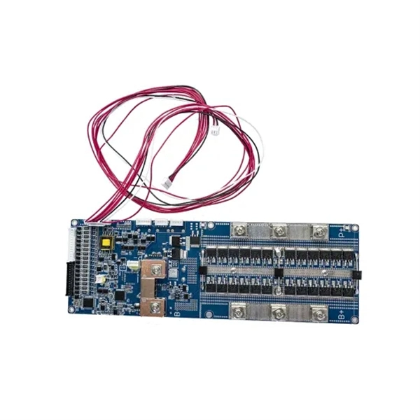
Unplug the electrical power cord of your BBU from the wall outlet. Open the battery cabinet on the BBU (you may need a screwdriver to do this). So, what DOES work for keeping track of your battery status? The right solution will help you solve the problems above without dooming you to the pitfalls above. Monitors the "Big 3" elements of battery health: voltage, temperature, and internal resistance. Provides 7x24x365 protection - without. This paper describes a step by step program of methods and procedures for maintaining the VRLA battery systems in the Local Exchange Carrier Central Office and Outside Plant Telecommunication Cabinet environments. Embracing these methods and procedures allows the user to obtain maintenance and test. Proper sizing of a telecom battery bank is essential for ensuring reliable power delivery and optimal performance. By calculating your energy needs and understanding the technical aspects of battery configurations, you can build a system that meets your requirements effectively. To size your. The DC Battery Module is a component of the DC power distribution panel for telecommunications that ensures the batteries fulfill. By understanding the methods for calculating battery capacity, charge/discharge rates, and cycle life, you can optimize the performance of your telecom cabinet power system and telecom batteries. Ensure the area is free from dust and vibrations, as these factors can affect the.
[PDF]