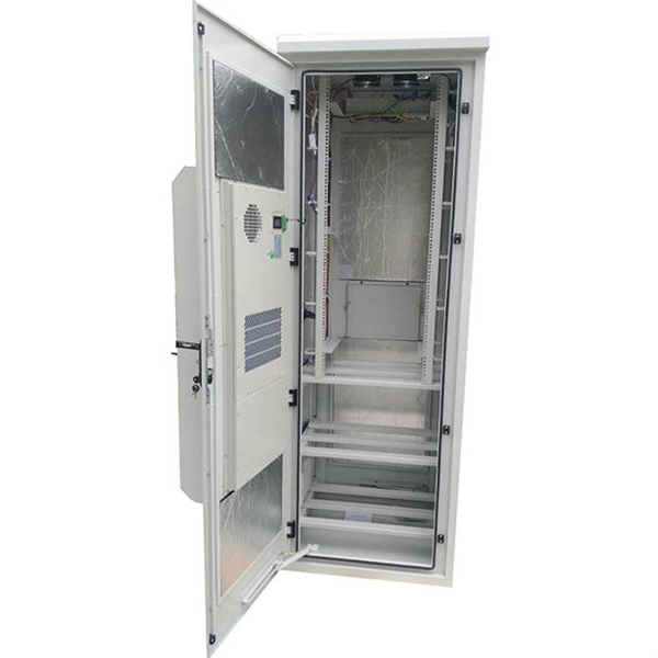
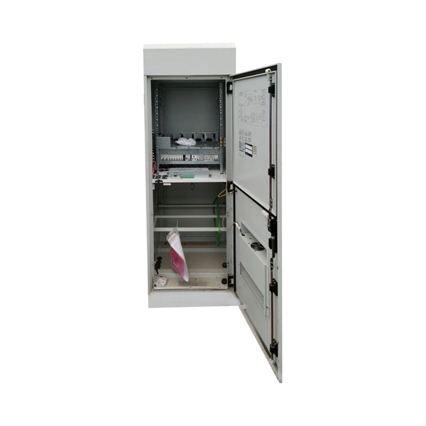
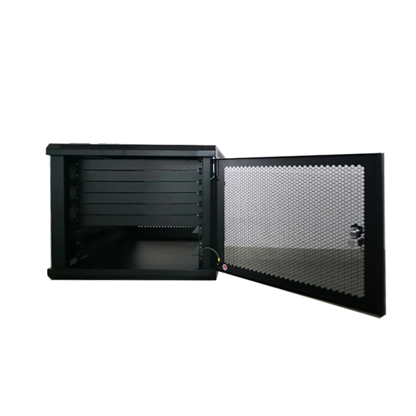
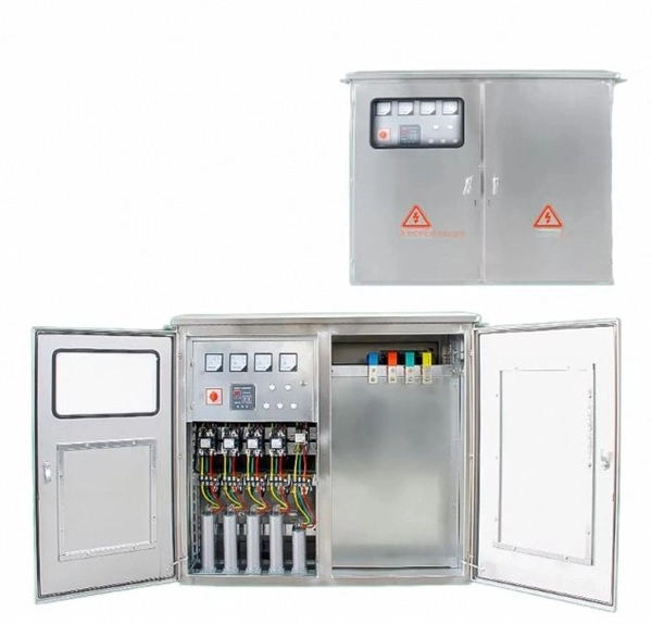
This guide provides a complete breakdown of enclosure types, materials, certifications, temperature considerations, and installation insights to help engineers, designers, and safety professionals select enclosures that meet both operational and regulatory demands. This system for explosion proof ratings uses Classes, Divisions, Groups, and Temperature Codes (T-Codes) to describe the type of hazard in the area and how often it occurs. Class: The general type of hazard present. Group: The specific type of. Specification code(I,II,IIB. Flameproof enclosure (Ex d IIB+H2), which can be used as feed distribution equipment in control and distribution system (such as distribution box, switch box of main circuit, control box, terminal box or motor starting box etc. ) ·Enclosure: stainless steel. Equipped. EN/IEC 60529 is a European and IEC standard that outlines the official method for classifying the effectiveness of electrical equipment enclosures in preventing the entry of foreign objects, like dust and moisture. What Are Hazardous Area. Options range from Ex d (flameproof enclosure) to Ex e (increased safety) and Ex i (intrinsically safe) right through to Ex p (pressurized housing), as well as combinations of different explosion-protection types – always bearing in mind the most efficient solution for your application. BARTEC. Durable Hexlon Explosion Proof Distribution Boxes and Electrical Enclosures, IECEx and ATEX certified for Zone 1 and Zone 2.
[PDF]

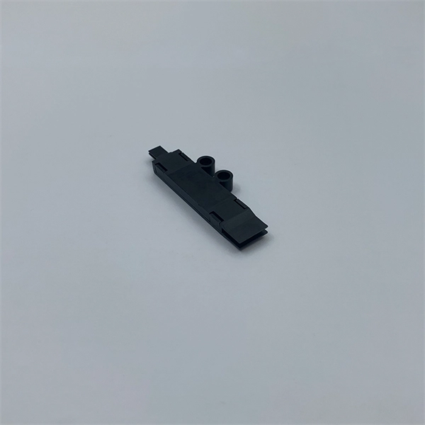
The socket accepts laser diodes with wire leads 24 to 26 gauge, 0. The maximum recommended current is 3 Amps. Specifications: Outside dimensions: 0. Thorlabs offers a versatile range of accessories for convenient integration of laser diodes into functional systems. These laser diode sockets are ideal for OEM-type implementations and are compatible with our selection of Ø3. 6 mm, Ø9 mm, and TO-5 laser diode packages. All of these sockets. Wide Range of Standard Products and Flexible Customization We offer a variety of standard products with different pitches, pin counts, and pin arrangements, helping to shorten lead times. Compatible with TO-18, TO-46, TO-52, TO-72, and more (please refer to the lineup at the bottom of the page for. Pricing (USD) Filter the results in the table by unit price based on your quantity. A tariff of 8% may be applied if shipping to the United States. A. Compact miniature socket size for maximum board density Accomodates most any TO package format with pin circle options of. The S8060 and S8060-4 sockets have a polarization dot on the top of. 4-Pins Laser Diode Test Socket High Precision Diode Test Stand 1. The inner hole of the pin is a through hole, and the length of the laser diode to be tested can be universal. The pins are made of gold-plated copper tubes, low resistance, not easy to oxidize, long service life.
[PDF]
Finally, we elucidate the latest developments and vital features of modern 850 nm VCSELs for high-speed interconnects. Introduction. Nedinsco delivers highly advanced optronic systems for reconnaissance and surveillance, trusted by military forces worldwide. Equipped with next-generation sensors, our systems significantly enhance visibility. We offer solutions for armored vehicles, unmanned ground vehicles (UGVs), drones (UAV's). Our company's advanced optoelectronic systems represent a technological leap forward in border security capabilities. Introduction Since the invention of the VCSEL by Iga's group in 1978 [1, 2] and the demonstration of its first room-temperature (RT, 300 K) operation in 1988 , many groups. Northern Macedonia has purchased three mobile surveillance and surveillance systems from the MUSON – MUSON 20FM series, developed by the Bulgarian company Opticoelectron, reports the BulgarianMilitary. Customized payload features, as well as FOG based stabilization provides ultra-long-range observation and tracking capabilities. The basic instruments like: VIS day camera, low light, SWIR camera, LWIR or. High-speed optoelectronics is central to many important developments in the communication, computing, sensing, imaging, and autonomous vehicle industries. With a sharp rise of attention on energy efficiency, researchers have proposed and demonstrated innovative materials, high-speed devices, and.
[PDF]

An Optical Splitter, also known as a beam splitter, is a passive optical device that divides a single input optical signal into two or more output signals. Conversely, it can also combine multiple signals into one. Knowing the difference between a splitter and an optical coupler helps you build better networks. You make your network work better when you pick the right device for each job. You can connect many users to one port with 1:n or 2:n splitters. By dividing a single optical signal from a central Optical Line Terminal (OLT) into multiple outputs for Optical Network Terminals (ONTs) at users' homes, splitters eliminate the need for dedicated fibers to each residence—slashing infrastructure costs while scaling network reach. This guide. In a Passive Optical Network (PON), a single optical fiber carries massive amounts of data using light. Signal Input: The fiber splitter receives the optical signal from the upstream network node and enters the splitter through the input fiber. Signal Distribution: Inside the splitter, according to the design structure and different. Splitters are passive optical devices that divide or combine optical signals, and they come in various types, including power splitters, uneven splitters, and wavelength-division multiplexing (WDM) splitters. Each type serves specific applications, enabling efficient use of optical infrastructure.
[PDF]

A ladder type cable tray tee is a fitting used to create a branch in a cable tray system, allowing cables to be routed in three directions. Its "T" shape provides a secure and efficient way to split cables from a main tray into two separate paths, ensuring organized and flexible. A cable tray tee and tee cover are components used in cable management systems to support and protect electrical and data cables. Here's a brief explanation of each:. Rigid steel cable tray tee fitting with zero tangent, safety bottom, and full accessory support. ventilation to heat producing cable such as power communication and other with the same or different width of the cable run. All fittings are available in sizes and types corresponding to the straight cable tray sections. These fitting are including: elbow, horizontal cross, vertical inside. NOTE : Equal or un equal tees can be supplied. When ordering state widths W1xW2xW3.. Office: 147/22 Nguyen Sy Sach Street, 15 Ward, Tân Binh Dist, HCMC,VN. Is it possible to connect 2 cabletrays with a "branch piece (left picture)" instead of a "tee (right picture)". The tee has 3 connectors, the branch piece only has 1 connector. I would like to ajust the "Type properties -> Fittings -> Tee" with the branch family, but can't get it accomplished.
[PDF]
The Climate Investment Fund (CIF) has given the green light to an $85 million investment for North Macedonia. The plan, under CIF's Accelerated Coal Transition Investment Program (ACT IP), is designed to trigger almost US$600 million. The Climate Investment Fund (CIF) has approved on Wednesday North Macedonia's investment plan for an accelerated energy transition from coal to clean energy, totalling €85 million. Skopje, 20 March 2024 (MIA) - The Climate Investment Fund (CIF) has approved on Wednesday North Macedonia's investment. WASHINGTON - Today, the governing board of the Climate Investment Funds, a pioneering multilateral climate fund delivering low-cost finance to over 70 developing countries, approved an $85 million investment plan presented by the Government of North Macedonia to transition away from coal and. WASHINGTON - Today, the governing board of the Climate Investment Funds, a pioneering multilateral climate fund delivering low-cost finance to over 70 developing countries, approved an $85 million investment plan presented by the Government of North Macedonia to transition away from coal and. The Climate Investment Funds Accelerating Coal Transition Programme (CIF ACT) offers a holistic toolkit to support countries transitioning away from coal, tackling challenges linked to national strategies, people, and communities, as well as land and infrastructure. With this approval, CIF delivers the first funding.
[PDF]
Find datasheets, CAD models, technical specifications, lifecycle and supply chain risk, stock and price history, and create alerts for parts. Note: Due to DigiKey value-add services the packaging type may change when product is purchased at quantities beneath the standard package. Order today, ships today. QL90R7SA – Laser Diode 905nm 200mW 2. 1V 250mA TO-56-3 Lens Top Metal Can from QSI Laser. Pricing and Availability on millions of. Pricing (USD) Filter the results in the table by unit price based on your quantity. A tariff of 70% may be applied if shipping to the United States. A. Variety of products with a power of 5 to 100 mW at 635 nm to 680 nm wavelengths Products with excellent reliability and low power consumption. QSI laser diodes come in several types. Here are the common types of these components. Continuous wave laser diodes emit a steady, unpulsed beam of light. com was created by ECIA in collaboration with participating distributors as a free service to support the authorized electronic components. QSI QL63I5S-A. 6mm.
[PDF]
This method statement describes a detailed procedure for properly installing cable trays and conduits for the Feeder System. It ensures that all installation activities follow authorized plans, specifications, and standards. Method Statement installation of Cable Trays and Ladders - Planning Engineer FZE. The Cable Tray system is installed in electrical rooms, plant rooms, and service. Keep your cables safe and organized with our high-quality cable trays. Cable Trays are important for ensuring the protection of the wiring system and supporting insulated electric cables used for distribution and communication. Brilltech Engineers Pvt. 6 mm thickness and complete with high tensile bolt, washers and nuts. Eight hardware sets of M8 size shall length of existing metal support structure (Length = approx. M-8 Galvanized/SS nut bol ressing the same HT cable. MP Husky Cable Trays are NEMA VE 2-2013 compliant. NEMA VE2 addresses cable tray installation and provides information on maintenance and system modification. NEMA VE2 was developed by the NEMA Cable Tray Section, of which MP Husky is a charter member. Proper planning for installing cable tray. Below is the detailed cable tray installation method statement not only for cable tray but also applicable for GI ladder and trunking for indoor and outdoor applications and in service rooms like pump rooms, electrical rooms and plant rooms etc.
[PDF]