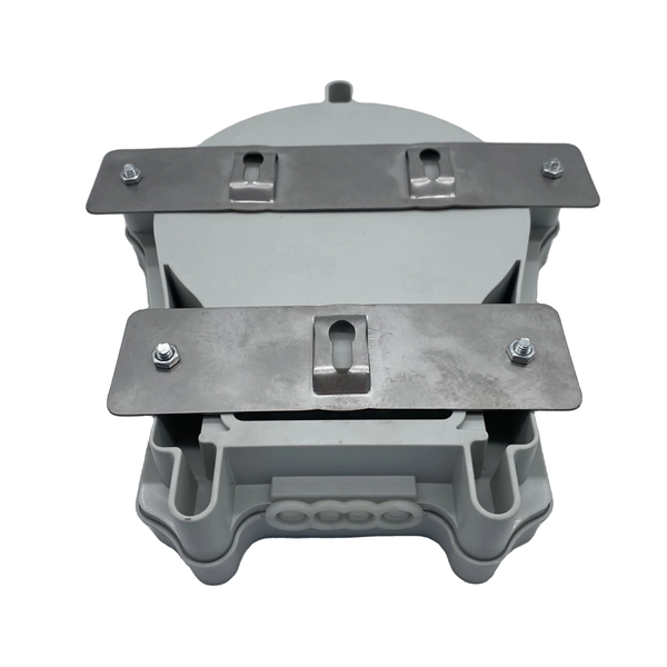
Professional-grade cantilever support arm specifically designed for cable tray installations. Features a welded flat mounting plate construction for secure attachment. Manufactured by nVent CADDY, this sturdy support solution provides reliable cable management infrastructure. 0 are currently in. 15. 41x21mm horizontal support for wall fixing of cable trays, electrical conduits and other heating pipe installations, A/C, fire protection systems, etc. Excellent loading capacity. Robust and secure system. Made of steel, available in various protection systems. Available in widths from 100 to 1000. Cable Support Systems are well designed to provide necessary support for cable trays, cable ladders and trunkings. Cable supports are manufactured according to common standards from high quality raw materials. Requires only one bolt for quick fixing and is used with open face at the top. Two bolt. us-trations without notice. All illustrations, descriptions and technical information included in this document are provided as indications and can cable trays are equivalent. The mechanical and electrical characteristics, tests, certifications, overall quality management, recommendations mentioned.
[PDF]
This article will focus on the failure rates of optical modules, analyze the primary causes of failure in traditional Digital Signal Processing (DSP) modules, compare failure rates utilizing LPO technology, and discuss the advantages presented by LPO modules. Linear Pluggable Optics (LPO) are a new optical transceiver technology. The idea is simple: instead of a DSP (digital signal processor) inside the module – replacing it with transimpedance amplifier (TIA) and a driver chip with high linearity and EQ capability – LPO shifts signal processing into. Copyright 2023, Coherent. Next-generation 400G and 800G modules for data centers, AI clusters, and telecoms — validated in a European lab, ready to ship from Europe. What is Low-Power Optical Transceivers (LPO)? Linear Pluggable Optics (LPO) replace the DSP inside the optical module with linear analog components, shifting. QSFP-DD LPO TRANSCEIVER DESIGNED FOR PCIE® GEN 5. 0 over optical link, enabling scalable server disaggregation and efficient rack-to-rack interconnects ideal for AI/ML and. Led by Cisco Optics experts, this MSA quickly gained broad industry support due to its vision to create cost-effective solutions for high-density multi-terabit switching, routing, and transport networks. The goal was to define optical specifications that allow for future 100G and 400G pluggable.
[PDF]
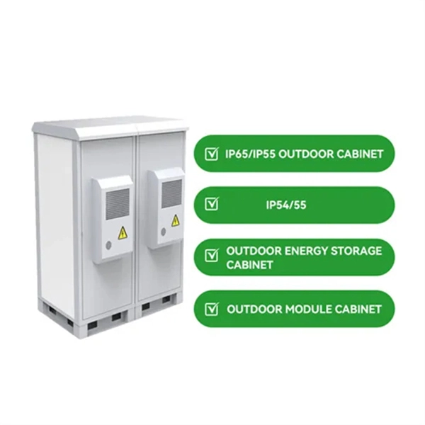
Step-by-step instructions on how to install the Polylok 12" distribution or drainage box. In this guide, we'll break down everything you need to know to install a distribution box correctly and confidently. Choose the right box based on environment (indoor/outdoor), load capacity, and durability. Check for proper IP/NEMA ratings and material quality. Ensure safe placement: install in. The installation of a distribution box is explored in detail, highlighting advanced techniques for achieving a professional and efficient setup. This video provides valuable insights for anyon. more Distribution Box Installation: Advanced Techniques. When it comes to rigid, easy to install electrical box supports, Eaton offers a wide variety of B-Lines series electrical boxes that help reduce installation complexity. For professional installers and property owners, the mechanical components like support rods play a critical role in long-term safety and maintenance efficiency. These components ensure that heavy-duty. Whether you are an electrical contractor or a construction brigade, knowing how to properly and safely install distribution boxes is the basis of ensuring the safe operation of the entire system.
[PDF]
Cable tray support quantity can be calculated using a simple formula: Support Quantity = Total Length ÷ Support Spacing + 1 20 ÷ 2 + 1 = 11 supports In a typical project, a 20-meter cable tray with 2-meter spacing requires 11 supports. As the industry leader in cable tray, Eaton offers one of the widest ranges of B-Line series cable management solutions available in the market today. With unmatched quality and service, we offer a variety of styles, materials and finishes available to support virtually any commercial and. When compared to conduit, cable tray and ladder allow for greater design flexibility and potential for cost savings. In complex engineering environments, the type of tray and installation conditions will directly influence the support quantity. Mastering the. Cable tray installation cost per meter varies by specifications; GangLong Fiberglass offers kits for raised floor system and facility needs. Cable trays are vital in electrical installations, providing secure pathways for power, communication, and control cables across residential, commercial, and. MP Husky Cable Tray support is engineered to provide rigid structural support and control for a variety of industrial and commercial installations. Layout isolation pads, (provided by contractor), according to the design and layout. Insert legs of duct support into bases and attach with 2-1/2” bolt and 1/2” nut.
[PDF]
This guide covers the critical steps, from selecting the right electrical cable tray and performing accurate cable fill calculations to managing a safe cable pull through and ensuring all bonding and grounding requirements are met. Article Summary: A compliant cable tray installation requires a thorough understanding of NEC Article 392, proper structural support, and precise installation techniques. But before you lay the first tray or clamp down a single cable, you need a solid plan. This guide breaks down the process step by step. Here is a step-by-step guide on how to install a standard metal cable tray system (e., ladder or perforated type). Before starting, ensure you have. NEMA VE2 addresses cable tray installation and provides information on maintenance and system modification. NEMA VE2 was developed by the NEMA Cable Tray Section, of which MP Husky is a charter member. Ladder Cable Trays Solid side rail protection and system strength with smooth radius fittings and a wide selection of materials and finishes. Maximum strength for long span applications. Welcome to our step-by-step guide on installing cable trays! In this video, we'll explore the different types of cable trays available and provide detailed instructions for their installation. Whether you're an experienced electrician or a DIY enthusiast, this video is perfect for you.
[PDF]
Leaders will gather at the World Economic Forum Annual Meeting 2026 to discuss how to protect the environment while also driving economic growth. The next phase of global growth will be shaped by digital intelligence and the energy infrastructure that supports it. The Global Energy Interconnection (GEI) Journal publishes original research on theories and developments as well practical applications on principles of large scale low carbon energy generation, transmission, distribution & storage technologies, global energy interconnection & system developments. The provision of low carbon energy to our society is a key issue at the heart of sustainable development of global energy supply. China's concept of Global Energy Interconnection recognizes the importance of energy inter-connectivity for clean energy transition and repre-sents one of the boldest visions for low-carbon development at the national, regional strial Revolution in the 1870s.
[PDF]

Cable tray support quantity can be calculated using a simple formula: Support Quantity = Total Length ÷ Support Spacing + 1 20 ÷ 2 + 1 = 11 supports In a typical project, a 20-meter cable tray with 2-meter spacing requires 11 supports. Calculating the cable tray support quantity is a crucial part of electrical installation projects. In complex engineering environments, the. Properly sizing your cable tray is critical for safety and compliance. Our free calculator helps you determine the correct tray size based on NEC and IEC standards. This calculator features an interactive interface with advanced visualizations. Open the full calculator for the best experience. Save your cable tray sizing calculator results as branded PDF. Calculate NEC-compliant wire basket cable tray fill, load capacity, and hardware requirements for professional installations. We independently provide precision steel tools, calculators, and expert resources for steel, metalworking, construction, and industrial projects. IEC 61537 covers cable tray and cable ladder systems for the support and accommodation of cables, while NEC Article 392 governs cable. What is the fill capacity and remaining capacity of my cable tray? Calculate cable tray sizing and fill capacity based on tray dimensions, cable diameter, number of cables, and maximum fill percentage per electrical code. Determine whether cables fit within safe fill limits. Cable tray fill.
[PDF]
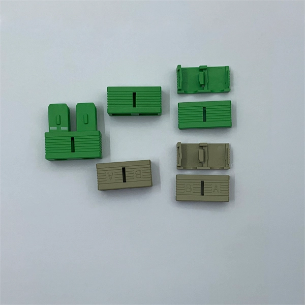
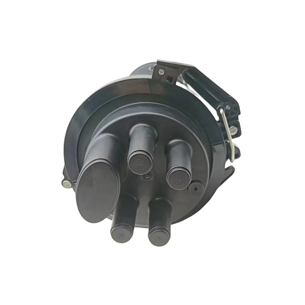
Used for hoisting cable trays under I-beams and U-shaped steel. Likely used for specific horizontal support. L-shaped metal profile for support or connection. Various customized brackets made from angle iron. When developing our cable support OBO can offer reliable solutions for systems, three attributes are at the routing and fastening cables securely core of what we do: efficiency, resil- for each of these installation challeng-ience and safety. es in the industrial environment. Our cable support. An electrical cable tray system serves as a rigid structural raceway designed to support and route electrical cables and wires. Unlike a simple wire trough, which is typically a covered channel for shorter runs, cable trays provide a comprehensive support system for complex wiring paths over long. This publication is intended as a practical guide for the proper and safe* installation of cable ladder systems, cable tray systems, channel support systems and associated supports. Cable ladder systems and cable tray systems shall be manufactured in accordance with BS EN 61537, channel support. maintain spacing or to keep cables in place when the tray is ect the minimum bend ra-dius for cables as they exit the bottom of the cable tray. These guidelines are not intended to cover all details or variations in cable ladder and cable tray.
[PDF]
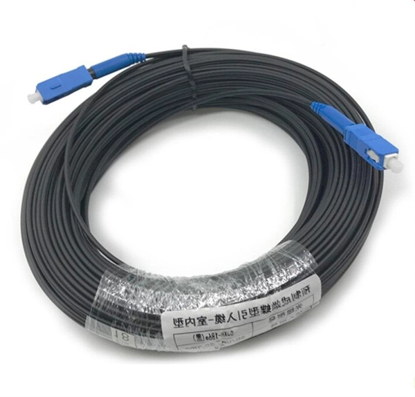
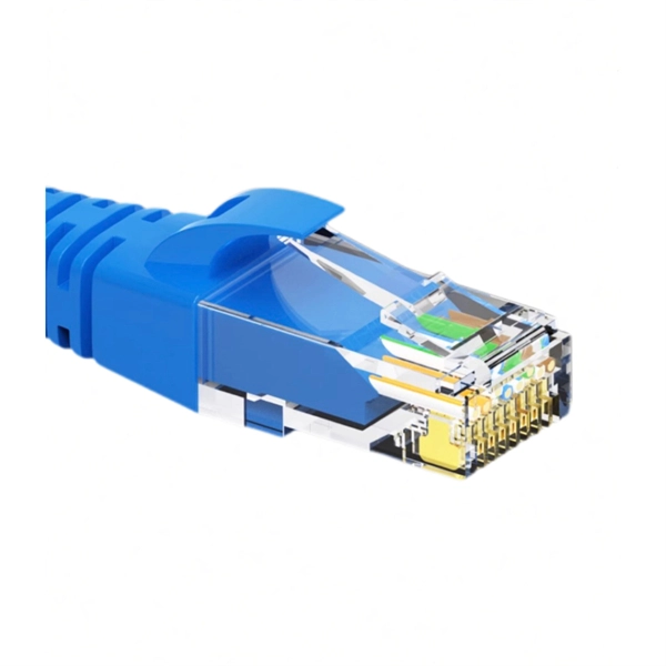
This video makes connecting your fiber optic cable to your router a breeze! We'll guide you through the entire process step-by-step, ensuring a smooth and hassle-free experience. Our Experts are helping user's, who are facing issues with their tech gadgets like. In this guide, we'll walk you through how to connect a fiber optic cable to a router safely and efficiently. Why Use Fiber Optic Internet? Before diving into the setup, let's quickly recap why fiber optics are worth the effort: Lightning-fast speeds (up to 1 Gbps or higher). Low latency for. Connect an Ethernet cable from the WAN port of your router to a LAN port on the Internet source (such as a broadband modem or fiber-optic modem). If you. This conversion happens either through an Optical Network Terminal (ONT) or directly via specialized router ports. Check compatibility: Before you begin, make sure your router supports fiber optic connection. Not all routers can connect directly to a fiber cable, so it is important to verify this information before continuing. Here's a step-by-step guide to help you through it. Understand the Basics Before diving in, familiarize yourself with the components involved:.
[PDF]

A switch must use optical or copper modules that have been certified for use on Huawei switches. Non-certified optical or copper modules cannot ensure transmission reliability and may affect service stability. Huawei is not liable for any problem caused by the use of non-certified optical or copper. The purchased products, services and features are stipulated by the contract made between Huawei and the customer. Unless otherwise specified in the contract, all. Compatible SFP transceiver supports up to 80km link lengths over single-mode fiber (SMF) using a wavelength of 1550nm via an LC connector. Each SFP transceiver module is individually tested to be used on a series of Cisco switches, routers, servers, network interface card (NICs) etc. It has minimum guaranteed optical budget of 25 dB, with in most cases is enough to reach about 40 km distance. However, distance is. We supply professional-grade optical networking components for ISPs, enterprises, data centers, and network installers across Kenya, and the Authentic Huawei 155M-1310nm-15km-SM-eSFP is a proven and trusted solution for reliable fiber connectivity. Huawei is globally recognized for its advanced. Introducing the Huawei OSC015B01, a cutting-edge optical transceiver designed for high efficiency and unparalleled performance. This eSFP module, with its Tx 1310nm/Rx 1550nm wavelength capabilities, is engineered for 155M operations, making it ideal for a variety of network enhancement tasks.
[PDF]
With up to 48 10 GE downlinks and 40/100 GE uplinks, the S6730‑H series supports bandwidth-hungry access and spine layers—perfect for Wi‑Fi 6 APs, 4K/8K video, and virtualization workloads. Based on Huawei's VRP OS, the series delivers OSPF, BGP, RIPng, IS‑IS, VRRP, and. This document provides campus networks typical configuration examples and feature typical configuration examples. "Campus Networks Typical Configuration Examples" provides typical campus network networking modes and a variety of deployment examples. Positioned perfectly as an Aggregation Switch or Core Switch, the S6730‑H delivers scalability, security, and cost-effectiveness for modern digital. The S5730-SI series switches are next-generation standard gigabit Layer 3 Ethernet switches. They can be used as access or aggregation switches on a campus network or as access switches in a data center. It also provides enhanced Layer 3 features and mature IPv6 features. eKitEngine S530 switches can be use in various scenarios. The S3700 utilizes cutting-edge hardware and Huawei Versatile Routing Platform (VRP) software to provide high-performance access and aggregation to an enterprise campus network.
[PDF]
Fiber optic cables cannot directly connect to the router. However, the router can work with a fiber optic modem. Helpful or not?. The WAN port can connect to a modem or the downlink LAN port of another router. The WAN port can also be used to connect an Ethernet cable with direct Internet access. You can use a. Step 1: Gather the Necessary Equipment To connect your fiber optic cable to a router, ensure you have the following: Fiber optic modem (ONT): Most fiber connections require an Optical Network Terminal (ONT), provided by your ISP. Compatible router: Verify that your router supports fiber optic input. This conversion happens either through an Optical Network Terminal (ONT) or directly via specialized router ports. This. You can use the AI Life app to complete initial configuration for your router. Connect an Ethernet cable from the WAN port of your router to a LAN port on the Internet source (such as a broadband modem or fiber-optic modem). This specialized equipment serves as the. Fiber internet transmits data using light signals through fiber-optic cables, which differs from traditional DSL or cable internet. Most fiber ISPs.
[PDF]
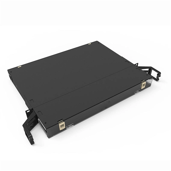
Step 3 Remove the cables or optical modules from the old card. Press the two green locking clips in the middle of the card to eject the ejector levers. Turn the ejector levers outward and slowly pull the card out. Place the replaced. Unplug the optical fibers from the optical module before removing it. Install or remove optical fibers carefully to avoid damaging the fiber connectors. If an optical module cannot be completely inserted into an optical. Page 7 Optical port USB storage device Wi-Fi terminal 1. Wear an ESD wrist strap or ESD gloves when replacing the optical module. Therefore, replace an optical module only when you confirm.
[PDF]
Introduces basic principles and application scenarios of the wired and wireless convergence feature supported by S series switches. Online view is not supported. Switch stacking is the process of combining multiple switches into a logical device that participates in data forwarding as a whole, in order to expand the number of ports, simplify networking, increase reliability, and extend the system's processing power and bandwidth. Moduletek Labs takes Huawei. Unless otherwise specified in the contract, all statements, information, and recommendations in this document are provided "AS IS" without warranties, guarantees or representations of any kind, either express or implied. effort has been made in the preparation of this document to ensure accuracy of. This document describes the best practices for stack deployment, including device selection, deployment, networking deployment, stack setup failures, and reliability. As flagship core switches in Huawei's CloudCampus portfolio, this series enables you to. The Huawei S2700 Series switches are a versatile collection of enterprise-level managed Ethernet switches, specifically designed to meet the needs of small and medium-sized businesses (SMBs). Featuring robust performance, simplified management, and advanced Layer 2 switching capabilities, the S2700.
[PDF]
Enable or disable the PoE function on S series switches: 1. system-view. Huawei's comprehensive portfolio of products and solutions enables you to realize smooth digital transformation and rapid growth of virtualization, Big Data, and cloud services. Huawei switches already help customers achieve success in industries such as finance, Internet, retail, education. Welcome to our user-contributed teardowns on the hottest new gadgets. You can write your own teardown, check out how others are contributing with their teardowns, and even check out disassembly photos and comprehensive hardware analysis. Why should I create a teardown? The Lenovo M910s has been. One of them in particular involves the use of Power-over-Ethernet (PoE), but as I don't already have any “standards-complaint” PoE equipment, I needed a cost-effective means of getting a workable set-up. In the early days of 100BASE-TX Ethernet, only two of four pairs of the Ethernet cable were. If one or multiple PoE chips of a PSE are suspended, the port connected to a PD cannot detect the suspension and fails to power the PD. In this case, you can reset the PoE chip. The PoE chip is reset. If PoE power modules are working normally, check whether the PoE card and DIMM are working normally. If the register. Only electrical interfaces of switch models with PWR or PWH in the device names support the PoE function. All views Before using the PoE function, run the display poe device command to check.
[PDF]