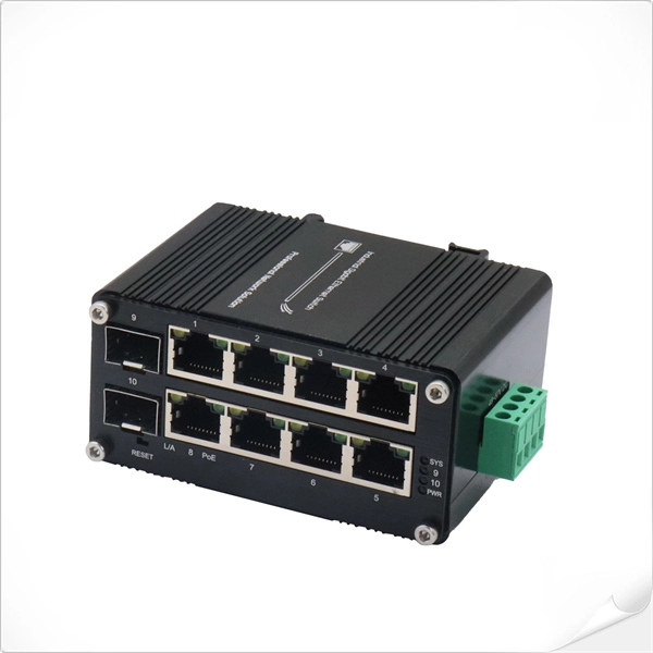
The SFP port is a built-in optical port of a Gigabit Ethernet switch, so it cannot be directly connected with a twisted pair or a jumper. It needs to be connected to an optical module first, and then it can be transmitted with an optical fiber patch cord. This chapter describes how to configure Gigabit Ethernet switching on the Catalyst enterprise LAN switches. Note For complete syntax and. Si ce produit est vendu au Canada, vous pouvez accéder à ce document en français canadien à https://www. com/support/download/. The RJ45 port is for copper cable. al installation guidelines and recommended procedures. To deploy this switch effectively and ensure trouble-free operation it is recommended to first read the relevant sections in this guide so rk administ tors and support personnel that install, e is based h relevant specif tions and. This command is configured in layer-2 interface configuration mode. The optical interface speed is fixed. The optical/electric port cannot support the gigabit and full-duplex at the same time. The ordinary TX port does not. The guidelines for configuring speed on QFX5100-48T switch are as follows: If the speed on the switch is set to 10-Gbps or auto, the switch advertises all the speeds. If you have configured the speed to 100 Mbps.
[PDF]
Unmanaged provides plug-and-play simplicity Auto-speed negotiation Selects individual port speed automatically, depending on client capabilities; removing the need for manual intervention enables simple.
[PDF]
Please select a category, brand, and model to find a type-approved device. Results will be displayed here after search. You can now apply and manage your RSB services online. Start today! The RSB Standards Store has a wide range of Standards covering various sectors and industries. Need help with any of your other applications? Apply for Zamukana Ubuziranenge and get assistance from our staff. Increase the. An LPO (Linear Pluggable Optics) solution offers considerable power savings for optical interconnect by removing the digital signal processing (DSP) function from the pluggable optical module. The idea is simple: instead of a DSP (digital signal processor) inside the module – replacing it with transimpedance amplifier (TIA) and a driver chip with high linearity and EQ capability – LPO shifts signal processing into. LPO (Linear-drive Pluggable Optics) is a transceiver packaging technology. It utilizes specialized components, including ASIC substrates, ASIC. In response, several solutions such as Linear Receive Optics (LRO), Linear Pluggable Optics (LPO) and Co-Packaged Optics (CPO) have been proposed. 1 shows the typical block diagram of a pluggable transceiver consisting of on-board lasers, optics, a Photonics die housing the modulator.
[PDF]

FS optical line protection switch features 1+1 backup and less than 15 ms fast switch to the standby fiber link that ensures business uninterrupted when malfunction occurs. An optical protection switch is a critical component in fiber optic communication systems designed to safeguard optical signals and infrastructure from damage due to power surges, signal overloads, or system failures. These switches ensure signal integrity, minimize downtime, and enhance network. 1+1 Optical Line Protection System for Fiber Protection, Bi-directional Protection in Dual Fiber, LC/UPC, Pluggable Module OLP (Optical Line Protection) is a device used in pairs, one at each end of the optical signal to protect network transmission line. OLP products include fiber optical line protection switches, optical bypass switches, optical cross connection, multi-channel. The FOSW-1x1 or 1x2 optical switch is based on opto-mechanical technology with proven reliability. OSW-W1x2 optical switch is a high performance electro-optical device, with low insertion loss (typic. In optical communication network, OLP monitors optical power of optical fiber and standby.
[PDF]
Step 3 Remove the cables or optical modules from the old card. Press the two green locking clips in the middle of the card to eject the ejector levers. Turn the ejector levers outward and slowly pull the card out. Place the replaced. Unplug the optical fibers from the optical module before removing it. Install or remove optical fibers carefully to avoid damaging the fiber connectors. If an optical module cannot be completely inserted into an optical. Page 7 Optical port USB storage device Wi-Fi terminal 1. Wear an ESD wrist strap or ESD gloves when replacing the optical module. Therefore, replace an optical module only when you confirm.
[PDF]

Shop network switches, including PoE, managed, unmanaged, and gigabit switches. Get high-performance connectivity with easy setup, competitive prices, and express delivery. An LPO (Linear Pluggable Optics) solution offers considerable power savings for optical interconnect by removing the digital signal processing (DSP) function from the pluggable optical module. This architecture takes advantage of the capabilities in each segment of the link to form a power, cost. One of the most groundbreaking network innovations driving transformations of data centers in 2025 is Linear Pluggable Optics (LPO)—a Digital Signal Processor (DSP)-free optical solution designed to optimize power, cost, and latency. At Dell Technologies, we are excited to offer fully supported. Upgrade your network with top-of-the-line switches. a wide array of high-performance network switches designed to enhance data transfer, improve efficiency, and ensure seamless connectivity. Linear Pluggable Optics (LPO) has emerged as a promising solution to address this challenge, offering a more efficient way to move data within server racks. Unlike its predecessor, Co-Packaged Optics (CPO), which integrates optical components directly into the electrical package, LPO focuses on. Simple and flexible solutions ideal for IoT deployments and out-of-the-wiring-closet setups. Operates on Cisco IOS Software, offering CLI and web UI for easy device and network management. Fast delivery across.
[PDF]

Optical switches will accept inputs nearly immediately as compared to mechanical switches, which could experience a few milliseconds of debouncing lag. Since optical switches do not depend on physical contact, input latency (latency) is severely minimized. This discrepancy can just be a couple of. An optical transistor, also known as photonic transistor, optical switch or light valve, is a device that switches or amplifies optical signals. Any communication protocol (Ethernet, ATM, etc. Significant. High Speed: Optical switches provide a high-speed data transmission capacity that surpasses that of traditional electrical switches. Interference Resistance: They are immune to electromagnetic interference, ensuring a reliable data transfer. Low Power Consumption: With no need for O-E-O conversion. Optical switching is the process of controlling the destination of individual optical information signals. This technology allows for high bit rate transmission to be switched between various optical lines. The core component enabling optical switching is the Optical Switch. Figure: Optical Switch. Serving as the backbone of high-speed fiber-optic networks, data centers, and emerging technologies like quantum communication, optical switches enable efficient light signal management with a small latency. As global demand for bandwidth surges due to 5G, AI, and cloud computing, advancements in.
[PDF]

Use two fibers: one dedicated to TX, the other to RX. Both sides transmit and receive at the same wavelength (common values: 850 nm MM, 1310 nm/1550 nm SM). The front panel is usually labeled TX and RX, and you cross-connect TX→RX, RX→TX with a duplex patch cord. Switch optical port intercommunication means that the optical fiber ports of two switches are connected to each other to achieve the purpose of network connection. The connection between two or more Ethernet switches in a certain way (Uplink port, etc. ) is called the cascade. SFP modules insert into these slots and and require two strands of fiber, typically duplex Using multi mode fiber (for runs under 1000 feet) or duplex single mode fiber (for runs over 1000 feet). This is a cost-effective and high performance way to connect network switches. Use one fiber strand for both. The switch supports 10 Mbps, 100 Mbps, and 1000 Mbps connections. Using Gigabit Ethernet (1000 Mbps), the switch sends files across the network at speeds up of to 2000 Mbps due to the full-duplex nature of Gigabit Ethernet connections. You can either connect 24 Ethernet copper cables or 22 copper. Port types are limited to two: optical and Ethernet. Optical ports on switches typically accommodate optical modules for transmitting data via fiber optic cables. In situations where there's a shortage of Ethernet ports, some users may insert Ethernet port modules into optical ports to connect with.
[PDF]
The QSFP28-100G-SR4 is a transceiver module designed for 100m optical communication applications. The design is compliant to 100GbASE-SR4 of the IEEE 802. 3-2012 Clause 88 standard IEEE 802. 100GBASE QSFP Active Optical Cable, 10m. 100GBASE QSFP Active. Each type provides information about the production during the forecast period of 2016 to 2027. Understanding the segments helps in identifying the importance of different factors that aid the market. TE SEACON is an industry leader in the design and manufacturing of underwater and subsea connectors, providing a comprehensive range of over 2,500 high-quality electrical and fiber optic connectors. The module converts 4 inputs. Global 100G Optical Transceivers Market Size By Product Type (Transceiver Modules, Active Optical Cables (AOCs)), By Interface Type (LC Interface, MPO Interface), By Application (Data Center, Telecommunication), By Transmission Distance (Short Range (up to 150m), Medium Range (up to 10km)), By Data. Modern data centers rely on high-speed optical links, and 100G optical transceiver modules (especially the QSFP28 form factor) are now foundational for this connectivity. 100G transceivers convert electrical signals to laser light over fiber, enabling top-of-rack switches to connect to aggregation.
[PDF]
In modern FTTH architectures, the ODN is the physical fiber layer that distributes optical signals from the central office to end users. Operators consider ODN design as one of the most important factors affecting: Network coverage Optical loss performance Deployment cost. This passive layer is known as the Optical Distribution Network (ODN). Its role is to provide an optical transmission channel between the OLT and the ONU. The ODN network design is a physical facility that connects the communication room and user equipment, and is a key component. Short summary: The Optical Distribution Network (ODN) is the passive infrastructure linking the central office to the subscriber in FTTH. This guide delves into essential ODN components like splitters, distribution boxes, and ODFs, showcasing how Hainan ZTO Cable Co. It's the silent, robust highway that delivers blazing-fast Fiber-to-the-Home (FTTH) and 5G services. The maximum permissible optical power attenuation between OLT optical ports to ONT input is 28dB, which is by utilizing the so-called Class B optical network. At the heart of every Fiber-to-the-Home (FTTH) deployment lies the Optical Distribution Network (ODN) — a meticulously engineered passive infrastructure that enables operators to deliver massive bandwidth, low latency, and reliable service to millions of users. The ODN connects the Optical Line.
[PDF]
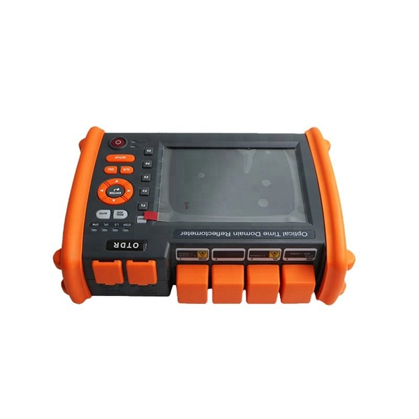
An optical time-domain reflectometer (OTDR) is an optoelectronic instrument used to characterize an optical fiber. It is the optical equivalent of an electronic time domain reflectometer which measures the impedance of the cable or transmission line under test. An OTDR injects a series of optical pulses into the fiber under test and extracts, from the same end of the fiber, light that is scatter. Reliability and quality of OTDR equipmentThe reliability and quality of an OTDR is based on its accuracy, measurement range, ability to resolve and. The common types of OTDR-like test equipment are: 1. Full-feature OTDR: 2. Hand-held OTDR and Fiber break locator: 3. RTU in RFTSs:. In the late 1990s, OTDR industry representatives and the OTDR user community developed a unique data format to store and analyze OTDR fiber data. This data was based on the specifications in GR-196, G.
[PDF]
As core components of optical communication systems, the proper installation and use of optical modules directly impacts network stability. The customer has 2 alarms on BTS3900 (GSM-R network). BBU Optical Module Transmit/Receive Fault 2. RF Unit Maintenance Link Failure The results of this alarms was restarting of the RF unit. After combining the RRU log analysis and the alarm of the optical module, the radio frequency maintenance. An alarm is generated when the transmit or receive power of an optical module is out of the allowed range. Indicates the MIB object ID of the alarm. Indicates the parent. After ruling out traditional problems like passive intermodulation (PIM), poorly aimed antennas and/or other coaxial problems, dirty fiber connectors account for 60 to 75% of the alarms, failures, and poor throughput problems found in modern cellular systems today. It has been several years since. All or part of the products, services and features described in this document may not be within the purchase scope or the usage scope. About This Document Introduction This document describes the routine hardware maintenance of the BBU3900. This article systematically identifies common anomalies during optical module installation. Combining hardware principles with practical experience, it.
[PDF]
An optical junction box is a vital component in fiber optic networks. It serves as a termination point for fiber optic cables, providing protection and distribution of the optical fibers while ensuring efficient signal transmission. Optical cable junction boxes play a crucial role in connecting and protecting optical fibers, directly influencing the quality and lifespan of optical cable routes. As the demand for high-speed internet and reliable telecommunications increases, the. What is an optical cable splice box Optical cable splice box is a popular name, its scientific name is optical cable splicing box, also known as optical cable splicing package, optical cable splicing package and gun barrel. It belongs to the mechanical pressure sealing joint system and is a splice. --- Optical Fibre Junction Boxes are critical components in the realm of telecommunications, serving as the interfacing point for optical networks.
[PDF]
Typically, an optical circulator consists of three main parts: wave plates, Faraday rotators, and birefringent crystals. When light enters the circulator, it is split into two beams with orthogonal polarization states. An optical circulator is a non-reciprocal device that directs light signals sequentially between multiple ports. You can think of it as a traffic controller for light, ensuring signals flow in one direction without interference. Unlike optical isolators that block reflected light, a circulator routes optical signals in a specific order — typically Port 1 → Port 2 and Port 2 →. An optical circulator is a three- or four-port optical device designed such that light entering any port exits from the next. This means that if light enters port 1 it is emitted from port 2, but if some of the emitted light is reflected back to the circulator, it does not come out of port 1 but. Optical Circulators are crucial components in modern optical communication systems, enabling the efficient routing of optical signals between different ports. In this comprehensive guide, we will explore the definition, basic principles, and importance of Optical Circulators, as well as their. The optical circulator is a fundamental device, acting as an advanced traffic controller that provides strict directional control over light signals within the network architecture.
[PDF]

There are different types of fiber optic cables because each type is optimized for specific applications that have unique requirements for bandwidth, transmission distance, and environmental factors. Fiber optic cables are often seen as the gold standard for network cabling. The choice of fiber optic cable depends on the specific needs of the application, as well as the. Optical cables, commonly known as TOSLINK cables, transmit digital audio signals using light, making them immune to electromagnetic interference that can affect the quality of analog connections. However, differences do exist among optical cables, and understanding these can impact your experience. Higher quality optical cables typically offer better signal transmission, durability, and reliability, making them a better choice for demanding. A fiber optic cable is a transmission medium that uses strands of glass or plastic fibers to carry data as pulses of light. It offers high bandwidth, low signal loss, and resistance to electromagnetic interference (EMI), making it ideal for modern high-speed networks. The Twisted Pair uses a copper wires to transmit a electrical signals offering the affordability and ease of a use in the local networks. Optical Fiber transmits the data via light pulses through the glass and.
[PDF]