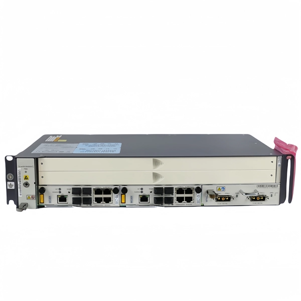
Includes dual power supplies, hot-swappable modules, link aggregation (LAG), and support for HSRP/VRRP. Modular chassis or stackable designs make it easy to scale as your network grows. 1X support, SNMP, CLI/Web GUI, and network access control. There are different types of enterprise switches that perform various roles in these layer-based or hierarchical ethernet networks. This white paper introduces the following three types of network switches and further discusses the selection criteria for each switch. What is a network switch? So, what is a network switch? A network switch is a vital component of a computer network that. What is Spanning Tree Protocol (STP) and why is it important in core switch networks? Can I use a cloud-managed core switch? How does Quality of Service (QoS) impact core switch performance? What Is a Core Switch in Networking? Understanding the Backbone of Your Network A core switch in networking. Providing The Most Competitive Networking Products For Global Customers! In the realm of system networking, three key types of switches are frequently mentioned: access switches, aggregation switches, and core switches. The part of the network that directly connects to user devices is referred to. What Is a Core Switch? The Definitive Guide to Network Architecture A core switch is a high-capacity, high-performance Layer 3 switch positioned at the physical backbone of an enterprise network. This post mainly explores the confusing problem: core.
[PDF]
There are connectors designed for single mode and multimode fiber optic cables, which differ in core size, bandwidth, and optimal use cases as explained in this comprehensive guide to fiber optic cable.
[PDF]
This list includes both standards-based and real-world technical cable types utilized in fiber-optic infrastructure, telecoms, enterprise, and outdoor applications. • OFC: Optical fiber, conductive• OFN: Optical fiber, non-conductive• OFCG: Optical fiber, conductive, general use.
[PDF]

The main group of impedance relays is distance protection devices. loss of synchronism protection, loss of excitation protection, or impedance automatics like fault locator. Impedance Relay Definition: An impedance relay, also known as a distance relay, is defined as a device that triggers based on the electrical impedance measured from a fault's location to the relay. Working Principle: The operation of an impedance relay hinges on the balance of voltage-induced. When a system has too many radial lines protection using time delay overcurrent relay becomes impractical. This problem can be solved to an extent by using distance relays. Distance relays uses voltage and current to calculate the. Distance relay protection has been defined as a part of relay protection in power systems that detects and isolates faults based on the distance between the relay and fault points. Unlike overcurrent relays, which only respond to the magnitude of current, a distance relay measures the impedance of. Such relays are called Distance Relays or Impedance Relays. In an impedance relay, the torque produced by a current element is opposed by the torque produced by a voltage element. The relay will operate when the ratio V/I is less than a predetermined value. The voltage transformer measures the voltage across the protected equipment, while the current transformer measures the current flowing through it.
[PDF]
There are two main types of RF attenuators: fixed and variable. Fixed Attenuators: Provide a fixed amount of attenuation, typically designed using discrete or chip resistors. These can be further divided into:. Attenuators are designed to change the magnitude of the input signal seen at the input stage, while presenting a constant impedance on all ranges at the attenuator input. A compensated RC attenuator is required to attenuate all frequencies equally. Without this compensation, HF signal measurements. Let's look at the common types of attenuators Fixed attenuators, as their name suggests, are fixed or unchanging. These are used in applications that don't require changing levels of attenuation or where an occasional replacement of one attenuator with another is acceptable. Say we now add a 6 dB pad between. An RF Attenuator is a two-port passive electronic device designed to reduce (attenuate) the power or amplitude of an RF signal. They can adjust the signal strength by controlling the amount of attenuation, ensuring that the signal reaches the desired level for transmission in a.
[PDF]
The WannaCry ransomware attack was a worldwide cyberattack in May 2017 by the WannaCry ransomware cryptoworm, which targeted computers running the Microsoft Windows operating system by encrypting data and demanding ransom payments in the form of bitcoin cryptocurrency. It was propagated using EternalBlue, an exploit developed by the United States National Security Agen. DescriptionWannaCry is a , which targets computers running the by encrypting (locking) data and demanding ransom payments in the. The attack began on Friday, 12 May 2017, with evidence pointing to an initial infection in Asia at 07:44 UTC. The initial infection was likely through an exposed SMB port, rather than as initially ass. Linguistic analysis of the ransom notes suggested the authors were likely fluent in Chinese and proficient in English, as the versions of the notes in those languages appeared to be human-written while the rest seeme. The ransomware campaign was unprecedented in scale according to, which estimates that around 200,000 computers were infected across 150 countries. According to, the four mo.
[PDF]
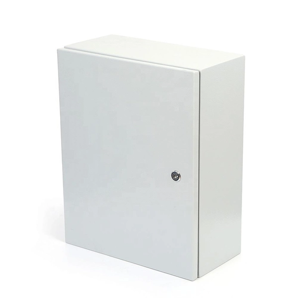
The BXM, BXD, and BXJ explosion-proof distribution boxes are engineered for the safe operation and control of specialized equipment in hazardous environments. Durable Hexlon Explosion Proof Distribution Boxes and Electrical Enclosures, IECEx and ATEX certified for Zone 1 and Zone 2. Order Explosion Proof Illumination Distribution Boxes from Warom Technology, a trusted manufacturer and supplier, designed for industrial lighting automation, hazardous electrical systems, nuclear illumination, defense applications, and waterproof, dustproof environments. ◆ The explosion-proof. It is widely used in flammable and explosive gas environment such as oil exploitation, refining, chemical industry, offshore oil platform, oil tanker, etc. Ideal for marine platforms, chemical tankers, LNG vessels, and dangerous cargo wharfs, these robust distribution boxes ensure reliable. Explosion Proof Box, SUREALL Low-voltage Control Guide Driving the state of the art innovation for power distribution and control for electrical equipment in harsh and hazardous location Explosion proof box, also called explosion proof boxes, include but not limit to explosion proof electrical. We supply certified explosion proof distribution box & Atex Transformer -Appleton, ATKON, CZ, CEAG, brands for safe and reliable industrial use.
[PDF]
Beam splitters are classified by construction (plate, cube, pellicle, polka dot) and by function (standard, non-polarizing, polarizing, dichroic). Construction determines ghosting, damage threshold, and form factor. Function determines how polarization and wavelength are. Beamsplitters are optical components used to split incident light at a designated ratio into two separate beams. Additionally, beamsplitters can be used in reverse to combine two different beams into a single one. Beamsplitters are often classified according to their construction: cube or plate. A beam splitter (or beamsplitter, power splitter) is an optical device which can split an incident light beam (e. a laser beam) into two (or sometimes more) beams, which may or may not have the same optical power (radiant flux). It is a crucial part of many optical experimental and measurement systems, such as interferometers, also finding widespread application in fibre optic telecommunications. It is also possible to combine the separated beams. Types of Beam Splitters 2. They are found in different configurations and can be used in multiple applications. However, how they work exactly often remains overlooked. These versatile tools can split both laser and regular light, depending on the application in question.
[PDF]
Fiber optic connectors can be categorized according to different standards such as utilization, fiber count, fiber mode, and transmission method. They are also divided into single-mode and multimode types based on their distinct characteristics. This guide will walk you through the most common fiber connector types, explaining their characteristics, advantages, and typical use cases. Whether you're planning an FTTH deployment, upgrading a data center, or working in telecom infrastructure, this guide will help you make informed decisions. Compared to Copper cables, Fiber connector types are incredibly varied. Where copper twisted pairs tend to terminate with an RJ45 plug, fiber optic connectors come in all sorts of shapes and sizes, with all manner of different use cases in mind. An optical fiber connector is used to join optical. With a wide variety of connector types available, choosing the right connector for your network can be challenging. Learn how each connector works, where it's used, and how to choose the right option for today's high-density, high-speed networks. It is a precise coupling device that joins fiber optic cables quickly, enabling faster connection and disconnection than splicing. The connector mechanically orients the fiber cores, allowing light to pass and travel through. In this guide, you'll explore various types of fiber optic cable connectors, each with unique features and best uses. We'll also provide practical advice.
[PDF]
This map shows where fiber internet service is available across the United States from all providers. Use the map controls to color by number of fiber providers or by maximum fiber speed available. Fiber-optic internet is the fastest and most reliable type of internet connection available. It uses. Let us show you the fiber data that is currently available! As one of the leading fiber location databases, FiberLocator conveniently provides you with detailed maps and information on hundreds of carriers, thousands of data centers and hundreds of thousands of on-net buildings to quickly grow and. Ask about ICT infrastructure, broadband data, or interact with the map. Show me range to terrestrial fiber nodes on the map? Is the ITU building in Geneva Switzerland within 10 km of a fibre node? Start measuring on the map to see calculations here. Analyze network nodes within a 10 km radius using. The most recent North American Fiber Deployment Report by RVA LLC Market Research & Consulting (RVA) released in January 2025 presented more records for the progress of fiber across America. A new annual record of 10. homes were passed in 2024. The FCC reviews the data and then publishes.
[PDF]

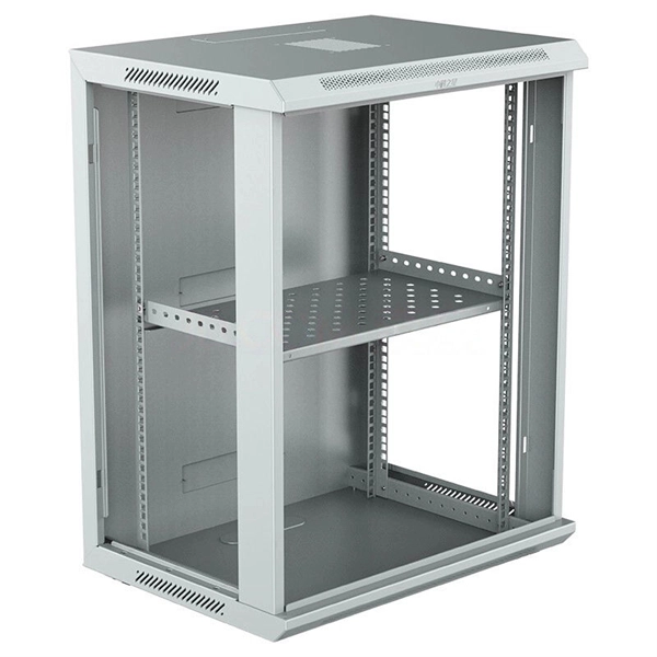
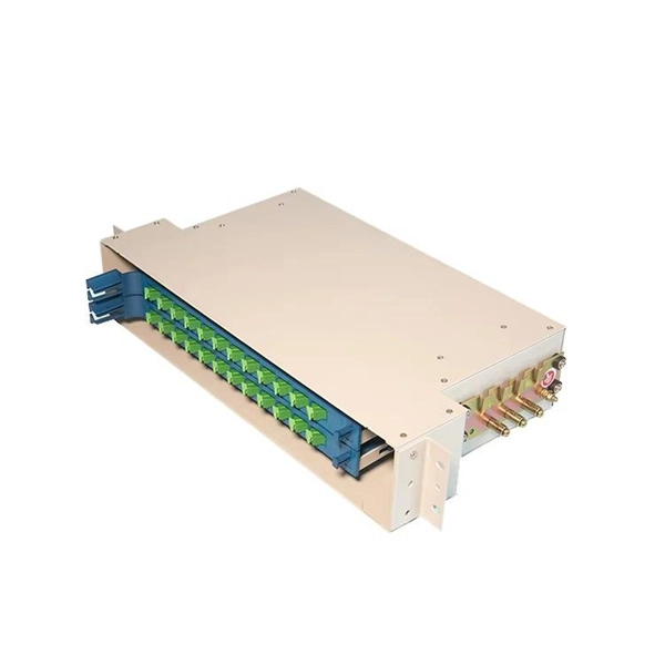
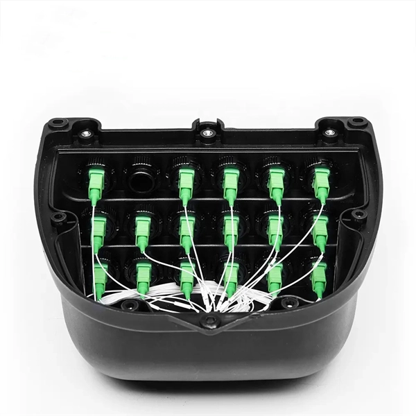
Quick answer: Choose a 12-port or 24-port ODF for small fiber terminations, branch locations, and light distribution needs. In real projects, the right optical distribution frame must match your current fiber count, rack space, adapter format, cable routing method, maintenance habits, and future expansion plan. Many buyers focus only on the initial number of terminations they need today. That often leads to one of two. An Optical Distribution Frame (ODF) is a metal unit that organizes fiber optic connections. It's where incoming and outgoing cables meet. Without it, cables get tangled. This article explores the types, components, applications, installation, and maintenance best practices, providing a. This complete guide explores everything you need to know about ODFs — from their structure, types, and key components, to installation best practices and modern design trends. Whether you're building a central office, data center, or FTTx distribution network, understanding the right ODF. This guide explores the various types of ODFs, their features, and ideal applications. Whether you're setting up a data center, deploying a telecom network, or managing fiber-to-the-home (FTTH) connections, understanding these types will help you select the right solution for efficient, reliable.
[PDF]
Electric power distribution systems are designed to serve their customers with reliable and high-quality power. The most common distribution system consists of simple radial circuits (feeders) that can be ove.
[PDF]
【Terminal Versatility】- Each 12V marine busbar features 5 x M6 (1/4”) stainless steel terminal studs for positive and negative connections, ensuring secure and efficient power distribution. Check each product page for other buying options. Price and other details may vary based on product size and color. Need help?. These bars are tin-plated copper and have stainless steel terminals. Also known as bus bars, they serve as connection points between wires with ring or spade terminals. The underside is sealed, so the bars can be safely mounted to conductive surfaces. Distribution Bar Covers— Distribution bar. Our automotive busbars and terminal blocks allow you to consolidate wiring and distribute electrical power in a cost-effective manner. So, what's the difference? A busbar. Pricing (USD) Filter the results in the table by unit price based on your quantity. Busbar Barrier Terminal Blocks are available at Mouser Electronics. Mouser offers inventory, pricing, & datasheets for Busbar Barrier Terminal Blocks. Pick compact mini bus bars, high amp PowerBar and MaxiBus models, and 4 to 20 circuit terminal blocks with covers for clean marine, vehicle, RV, and bench wiring. Shop terminal blocks, barrier strips, and DC bus bars.
[PDF]