How to install a fiber optic cable into a patch panel. Fibre Optic Patch Panel Installation Fibre Optic Cabling Know How - how to connect Fibre Optic Cable to a Patch Panel This video shows you how to install. Fiber optic patch panel is a crucial component in optical communications networks. It also known as a fiber patch panel or fiber distribution panel. It serves as a central point for organizing, managing, and connecting fiber optic cables. At its core, a fiber optic patch panel acts as a hub for. What are the best practices for fiber patch panel installation? The best practices below help to avoid installation issues and ensure ease of service for the system. Penetrate the enclosure from the side or bottom to minimize the risk of water intrusion. Step 1: Gather the Tools and Equipment The first step in connecting. How to Install a Fibre Optic Cable into a Patch Panel ( Fibre Optic Patch Panel ) How to install a fiber optic cable into a patch panel. This is essential for streamlining network. Running fiber internally involves extending this high-speed link from the service entry point to a centralized location, such as a dedicated media closet or network rack. This DIY effort is undertaken to maximize performance, improve aesthetics, or relocate the Optical Network Terminal (ONT) to a.
[PDF]
A8: Yes, multimode fiber optic cable can support high-speed data transmission depending on the fiber type and network equipment used. Multimode fiber (MMF) is an optical fiber designed to carry multiple light propagation paths—or modes—simultaneously. This is made possible by its relatively large core diameter, typically 50 or 62. 5 microns, compared to the ~9-micron core in single-mode fiber. The wider core accepts light from. Multi-mode optical fiber is a type of optical fiber mostly used for communication over short distances, such as within a building or on a campus. Multi-mode links can be used for data rates up to 800 Gbit/s. Multi-mode fiber has a fairly large core diameter that enables multiple light modes to be. In the realm of telecommunications and networking, multimode fiber optic cable plays a crucial role in efficiently transmitting data over short to medium distances. This guide aims to provide a concise understanding of multimode fiber optic cable and its applications. These fiber cables are structurally designed to transmit several light signals simultaneously, each of which is directed. Unlike copper cables, which rely on electrical signals, fiber optics use pulses of light to transmit data—offering unmatched bandwidth, low interference, and long-distance capabilities. But not all fiber cables are created equal: multimode (MM) and single mode (SM) fibers are the two primary types.
[PDF]
Single mode and multimode fiber optic cables are two different types of fiber optic cable aimed at different use cases. Single mode cables are typically made with a single strand of glass at their core, leading to a n.
[PDF]
Join Jake from Omnitron in this comprehensive tutorial. Understand the nuances of single-mode and multimode fibers, and how to bridge the gap using media converters. Enhance your tech knowledge and. But what happens when you need to connect an existing multi-mode campus network to a new single-mode service provider link? You can't just splice them together. This is where fiber conversion comes in. This guide will break down the professional methods to achieve seamless single-mode to multi-mode. Single-mode (SMF) and multi-mode fiber (MMF) use different core sizes, sources and wavelengths. These differences determine which transceivers work with which fiber and how far signals can travel. Let's analyze the differences between multimode and single-mode fiber to understand why networks require fiber mode conversion and. How can we convert the multimode to a singlemode fiber system? This complete guide will provide answers to these questions. That is because SMF and MMF have. There are two main types of fiber optic cables: single mode and multimode. Although they can do the same job in some instances, the different construction methods make each of them better suited to certain tasks and budgets. What if end B is located in another building, dozens of kilometers far away from end A? Or end B equipment is single-mode or must use a single-mode fiber connection? In the former case, you.
[PDF]

Fiber optic patch cabling is part of a fiber optic network construction, so the important choice is whether to use multimode patch cords or single mode patch cords. These patch cords aim to achieve the same goal of transmitting optical signals by the means of the construction, performance, and. Fiber optic patch cords, also known as fiber optic patch cables or fiber jumpers, are indispensable components in modern optical networks. They act as the critical link for interconnecting devices like optical switches, servers, and distribution frames. Understanding the various technical. This guide explains what fiber patch cables are, their types, connector standards, where they are used, and how to choose the right one for your data center. It is designed for flexible. But believe it or not, it's very possible that single mode fiber cables are the best option for you. While it is true that multi mode fiber optic cords are better at handling a heavier load than single mode cables, especially where a complex data network is involved, there are some situations where. When it comes to fiber optic patch cords, two primary types are single-mode and multi-mode. Single-mode fibers are designed to carry a single mode of light, allowing for higher bandwidth and longer transmission distances compared to multi-mode fibers. Singlemode fiber optic patch cables support high-speed networks up to 50 times farther than.
[PDF]
Single mode and multimode fiber optic cables are two different types of fiber optic cable aimed at different use cases. Single mode cables are typically made with a single strand of glass at their core, leading to a n.
[PDF]
A fiber-optic switch allows you to connect two or more fiber-optic cables to form a network. These can behave like a typical Ethernet switch. With a fiber switch combined with a fiber network adapter, you could connect fiber directly to your desktop computer or. Multimode fiber (MMF) is an optical fiber designed to carry multiple light propagation paths—or modes—simultaneously. This is made possible by its relatively large core diameter, typically 50 or 62. 5 microns, compared to the ~9-micron core in single-mode fiber. The wider core accepts light from. Multi-mode optical fiber is a type of optical fiber mostly used for communication over short distances, such as within a building or on a campus. Multi-mode links can be used for data rates up to 800 Gbit/s. Assuming Auto-MDIX is not enabled on these devices, drag the appropriate type of cabling on the left to each connection type on the right. In this blog post, we will discuss the key features and. This article describes the common types of fiber optic cable used for data transmission. Ubiquiti also provides branded optic SFP/SFP+ modules (tranceivers) that are fully compatible with all of our devices. See the page for more information. Back to Top Fiber optic cabling is an alternative to.
[PDF]
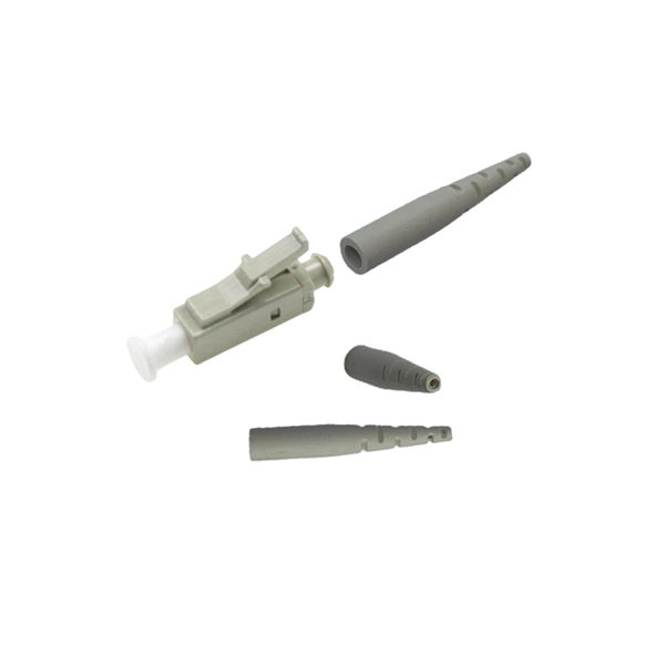
Fiber optic connectors, also known as terminations, connect two ends of fiber optic cables. A fiber optic connector is a mechanical device used to align and join optical fibers, enabling light to pass through with minimal loss. Unlike fiber splicing, which is permanent, connectors allow for easy connection and disconnection of cables, making them ideal for maintenance and flexibility in. This article provides a complete, practical guide to choosing the right fiber optic connector for modern networks. It explains all major connector types (LC, SC, MPO/MTP, ST, FC, rugged industrial connectors), the differences between simplex/duplex, single-mode/multimode, boot types, polish types. Where copper twisted pairs tend to terminate with an RJ45 plug, fiber optic connectors come in all sorts of shapes and sizes, with all manner of different use cases in mind. However, with several connector types available, each with unique designs and uses, it's important to understand which one fits your application best. In this. Picking the most appropriate fiber cable connector type from the numerous optical connector types available has a direct bearing on network performance, scaling up, and ongoing maintenance. The connector features a ferrule, the connector end piece that holds and secures the fiber and aligns it for light.
[PDF]
Browse different network patch panel icons in unique different design styles. Patch panels are one of the best ways to manage an expansive local area network (LAN) by providing quick and easy access to the ports and connections that connect them altogether. They come in a range of sizes, and are typically mountable, whether that's on a wall, or on a rack to make for easier. Browse 10000 different network patch panel icons in 151 unique design styles. Download network patch panel icons. ICC's patch panel color icons were created to provide an easy color identification system specially designed for our cross-connect patch panels. They are available in nine colors. ITEM NUMBER DESCRIPTION ICMPPSCIxx* VOICE icons and DATA icons 6 pcs. ICMPPICVxx*. Icons (33) Photos. Find 33 Network Patch Panel images and millions more royalty free PNG & vector images from the world's most diverse collection of free icons. Get free icons of 48 patch panel in style for your design. You're also welcome to check new icons and popular. design styles for web or mobile (iOS and Android) design, marketing, or developer projects. These royalty-free high-quality Patch Panel Icons are available in SVG, PNG, EPS, ICO, ICNS, AI, or PDF and are available as individual or icon packs. You can also customize them to match your brand and.
[PDF]
In cities, fiber optic splice boxes are installed on utility poles or underground conduits to connect multiple buildings and service providers. They enable high-capacity internet, TV, and phone services. AFL's "Fiber-in-a-Box" solution offers contractors lightweight, easy to use cable packaging with "out of the box" disbursement of fiber cable. No reel supports or pay-off's are required. Simply set the box down in a convenient place, unlock the built-in braking mechanism and begin pulling. Adjust. Fiber optic splice boxes are essential components in the world of telecommunications and data infrastructure. They serve as protective enclosures where fiber optic cables are joined, split, or terminated. They function as junction points that manage, protect, terminate, and distribute fiber optic cables, ensuring efficient data transmission between different. Check each product page for other buying options. Fiber Optic Wall Mount Box with LC Couplers for Single Mode & Multimode Fiber Optic Cable. | Fiber Box Enclosure for MPOE's, Network Rooms, and IDF Rooms. Get 36 LC connectors in one pre-wired OM3 fiber cassette. Snap into unused slots in your enclosure. This product replaces the JPM408A-R2. Accept up to 48 fibers housed within a 1U space. ITEM# JPM390A, JPM395A. A fiber optic distribution box, also known as a fiber optic terminal box or termination box, is a device used to connect and manage fiber optic cables within a network.
[PDF]
The short answer is no - RJ45 connectors are designed for electrical Ethernet signals, while fiber optics transmit light pulses through glass or plastic. However, modern networks often combine both technologies. Fiber optic internet is a high-speed, reliable solution for modern connectivity, offering superior performance for both residential and enterprise networks. Fiber optic technology is a method of transmitting information from one point to another using light signals that are transmitted along thin, flexible fibers made of glass or plastic. It has become an essential component of our daily lives, providing fast and reliable communication over long. This tutorial explains the types of network cables used in computer networks in detail. Learn the specifications, standards, and features of the coaxial cable, twisted-pair cable, and fiber-optical cable. To connect two or more computers or networking devices in a network, network cables are used. Network cable connectors have various types and work for certain purposes. This article is a complete guide. It will give you an overview of these types and describe how they work. The fundamental difference between optical fiber and Ethernet cables is that optical fiber cables transmit data using light signals, while Ethernet cables transmit data using.
[PDF]
Patch panels remain indispensable for medium-to-large networks due to their cost savings, flexibility, and organization benefits. However, scalability constraints and niche applications require careful planning. A patch panel is one of those components that is easy to overlook when planning a network — it does not switch, route, or process data, and to the uninitiated it can look like an expensive way to add an extra set of connectors between the cable and the switch. In practice, it is the component that. A patch panel is a centralized hardware component used to manage network cables in data centers, enterprise server rooms, and smart buildings. According to Grand View Research, the global structured cabling market is projected to reach $15. 6 billion by 2030, with patch panels playing a pivotal role. That's where patch panels come in. In this blog, we'll. Patch panels help achieve this by organizing connections, simplifying maintenance, and improving overall cable management in structured cabling systems. Disclosure: As an Amazon Associate, this site earns from qualifying purchases. Whether in data centers, business or home networks, patch panels streamline cable management, improve troubleshooting and enhance overall network performance. Let's learn more.
[PDF]
In an Ethernet patch panel diagram, each port on the patch panel is represented by a numbered or labeled square or circle. The diagram typically includes details such as the port numbers, cable types, and the devices connected to each port. Ethernet patch panel diagram is a visual representation of the connections between Ethernet cables and network devices, such as switches and routers. It provides a clear overview of how the network is structured, allowing network administrators to easily troubleshoot and manage the network. This information can be used to track the location of devices, their serial numbers, and their IP addresses. Change Management: Patch panel connection diagrams can be used to track. A patch panel is an essential component in a network system that provides a central location for connecting multiple devices or cables. The patch panel serves as. A pair of managed Gigabit Ethernet rack-mount switches, connected to the Ethernet ports on a few Panduit patch panels using Category 6 patch cables. (All equipment is installed in a standard 19-inch rack. Each port has a patch connection that links it to another port in another part of your building.
[PDF]
The Gateway Cities Council of Governments' (GCCOG) Gateway Cities Fiber Optic Network Project will expand fiber optic infrastructure, aiming to establish a new regional fiber network to address the digital divide and provide high-speed internet access. The FOA created its Online Reference Guide to provide a more up-to-date and unbiased reference for those seeking information on cabling and fiber optic technology, components, applications and installation. It's success confirms the assumption that many users prefer the Internet for technical. Building a fiber optic network is a highly technical yet vital process that enables communities and businesses to access high-speed, reliable fiber optic internet. From the initial site survey to the final fiber to the home (FTTH) connection, every stage requires careful planning, coordination, and. Fiber optic network design is not simply a theoretical framework—it is a disciplined engineering process that determines how infrastructure will perform, scale, and be maintained over the next 20 to 30 years. The project involves building significant.
[PDF]

The max insertion loss of a fiber patch cable is 0. 75 dB (the maximum acceptable value) in the TIA standard. Insertion loss (IL) and return loss (RL) are key performance indicators of fiber optic patch cords. This article explains their concepts, standards, testing methods, and FiberMania's quality assurance workflow to ensure optimal network performance. Fiber optic patch cords are crucial components in. A: Fiber optic loss refers to the reduction in signal strength as it travels through the fiber optic cable. This can be due to various factors, including attenuation, connectors, and splices. Q: How is fiber optic loss measured? A: Fiber optic loss is typically measured using an Optical Loss Test. The estimate, called a "loss budget" is calculated using typical component losses for each part of the cable plant - the fiber, splices and/or connectors. If the measured loss exceed the calculated loss by a significant amount (remembering the inherent uncertainty in all measurements), the system. Insertion loss is usually shortened to IL, and the unit of measurement for insertion loss is dBm. ) in transmission systems. It is the power attenuation of the signal after. At TARLUZ, we specialize in manufacturing high-performance fiber optic patch cords that comply with global industry standards, ensuring optimal signal integrity and long-term stability.
[PDF]