The procedures in this document describe basic inspection techniques and processes of cleaning for fiber optic cables, bulkheads, and adapters used in fiber optic connections. Note: This document is intended for use by service personnel, field service technicians, and. There are three main principles that needs to be taken in consideration for an efficient optical connection: a perfect core alignment, perfect physical contact and dirt-free connectors. It is important that every fiber connector be inspected and cleaned prior to mating. That advice is misguided. It could hurt an installer or get them sued by an irate network owner. This guide outlines best practices for maintaining and inspecting installed fiber optic infrastructure, enabling network owners to keep their systems running at peak efficiency. Fiber optics infrastructure consists of optical fiber cables, connectors, splice enclosures, distribution panels, and. Small oil micro-deposits and dust particles on fiber optic cable optical surfaces may cause a loss of light or degraded signal power which may ultimately cause intermittent problems in the optical connection. Fiber optic testing and maintenance protocols not only maintain the reliability of the network, but also allow for early detection of potential failures and optimization of performance.
[PDF]
For steel pipe piles, strain sensing FO cables with steel strands are generally installed on the steel pipe surface using welding and cementation. Then the pile is slowly driven into the soil layer. The installatio.
[PDF]

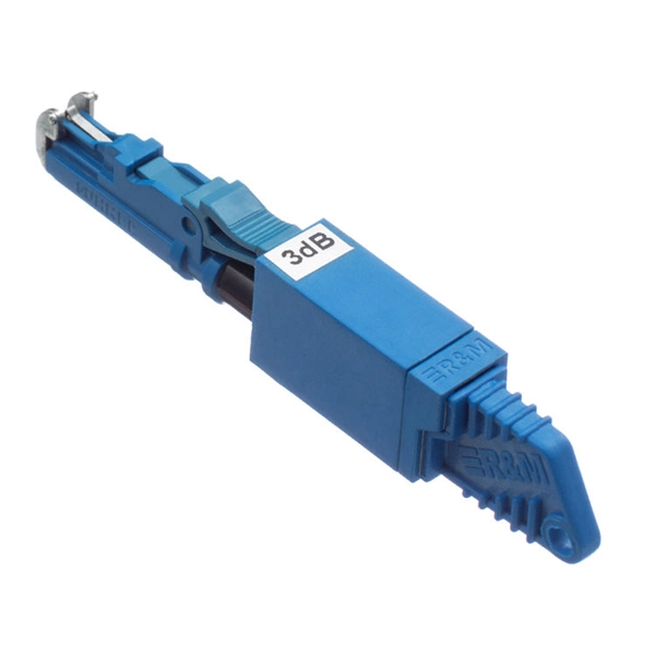
In this case use an optical power meter (OPM) and test the input port of the splitter for the optical power level (dBm) from the OLT at 1490 nm. If there is no or reduced power then the patchcord or OLT is the culprit. If the power level is reduced it could be as simple as a. So for this simple 1X2 splitter, how do we test it? Simply follow the same directions for a double-ended loss test. Attach a launch reference cable to the test source of the proper wavelength (some splitters are wavelength dependent), calibrate the output of the launch cable with the meter to set. Optical splitters in the outside plant (OSP) are used mostly in passive optical networks (PONs) for fiber-to-the-user (FTTx) networks, and are often overlooked as failure points. In this article I focus on a few basics of optical splitters, their applications, typical causes of failures, and how to. Now, we test the simplest 1x2 optical splitter as the picture shown below. 001 dB), OTDR (for reflection event detection). Cleaning tools. The CertiFiber® Pro Optical Loss Test Set (OLTS) can be used to check that the loss of a PON Splitter (often referred to in various standards as a non-wavelength-selective or wavelength-selective branching device) to check that it is within the allowed defined limits. The CertiFiber® Pro has an.
[PDF]
A solar meter, also known as a solar irradiance meter or pyranometer, is a device that measures the amount of solar energy or irradiance emitted by the sun. It is commonly used in solar power applications to op.
[PDF]

The socket accepts laser diodes with wire leads 24 to 26 gauge, 0. The maximum recommended current is 3 Amps. Specifications: Outside dimensions: 0. Thorlabs offers a versatile range of accessories for convenient integration of laser diodes into functional systems. These laser diode sockets are ideal for OEM-type implementations and are compatible with our selection of Ø3. 6 mm, Ø9 mm, and TO-5 laser diode packages. All of these sockets. Wide Range of Standard Products and Flexible Customization We offer a variety of standard products with different pitches, pin counts, and pin arrangements, helping to shorten lead times. Compatible with TO-18, TO-46, TO-52, TO-72, and more (please refer to the lineup at the bottom of the page for. Pricing (USD) Filter the results in the table by unit price based on your quantity. A tariff of 8% may be applied if shipping to the United States. A. Compact miniature socket size for maximum board density Accomodates most any TO package format with pin circle options of. The S8060 and S8060-4 sockets have a polarization dot on the top of. 4-Pins Laser Diode Test Socket High Precision Diode Test Stand 1. The inner hole of the pin is a through hole, and the length of the laser diode to be tested can be universal. The pins are made of gold-plated copper tubes, low resistance, not easy to oxidize, long service life.
[PDF]

Fiber optic connector pull test demonstration with real-time insertion loss monitoring. We use an optical loss tester to track signal stability every second while controlled tension is applied to the fiber. more. Fiber optic cable is surprisingly strong, durable and pliable; however, several best practices should be followed to ensure a successful cable installation. The below article explores the best practices and tools commonly used to pull fiber optic cable. The Future Ready Solutions Tools & Test. NEOFIBO TFTM-100N Vertical Fiber Optics Cable Tension Testing Machine The Cable Tensile Testing Machine is a precision mechanical measuring instrument designed to evaluate the tensile strength and elongation properties of various cables, wires, and fiber optic assemblies. Most fiber damage does not come from normal operation after the system is live. It happens during installation, when excessive pulling force, tight bends. Fiber optic connectors are designed to be connected and disconnected many times without affecting the optical performance of the fiber circuit. Optimal performance can be achieved by following the correct process for termination of the fiber circuit—a task which requires the use of a wide range of. The Fluke Networks JR-LEV-1 JackRapid Punch Down Tool is a cable termination tool that is designed to give technicians maximal efficiency in cable maintenance.
[PDF]

The fastest way to test a fluorescent tube is with a multimeter set to continuity mode. Each end of the tube has two pins connected by a thin filament inside the glass. If either filament is broken, the tube is dead. The whole test takes about 30 seconds per tube once you know what. This is a complete guide for testing a fluorescent light bulb with a multimeter. You don't have to be an expert in electrical work. This process measures electrical resistance to determine if the tube has suffered an internal failure before replacing the bulb or investigating the ballast. This guide provides a comprehensive understanding of the process, equipping you with the knowledge and. To test a fluorescent light bulb, observe any of the following: flickering light, low brightness, buzzing sound, delayed start, and fading color and light variation. Turn off the power to the circuit that powers the fixture and keep the leads steady to ensure accurate readings. Multimeters provide. How to Test Light Bulbs & Fluorescent Tubes with a Multimeter (Continuity Check) Is your lamp or fixture failing to light up? Before you buy a new bulb, you need to confirm if the bulb or tube itself is the problem! A simple continuity check using a multimeter can instantly tell you if the filament.
[PDF]
A beam splitter or beamsplitter is an optical device that splits a beam of light into a transmitted and a reflected beam. It is a crucial part of many optical experimental and measurement systems, such as interferometers, also finding widespread application in fibre optic telecommunications. DesignsIn its most common form, a cube, a beam splitter is made from two triangular glass which are glued together at their base using polyester,, or urethane-based adhesives. (Before these synthetic,. Beam splitters are sometimes used to recombine beams of light, as in a. In this case there are two incoming beams, and potentially two outgoing beams. But the amplitudes. For beam splitters with two incoming beams, using a classical, lossless beam splitter with Ea and Eb each incident at one of the inputs, the two output fields Ec and Ed are linearly related to the inputs thro.
[PDF]

In this guide, you will learn how to interpret network diagrams like a pro, from symbols and scope to segmentation, dependencies, troubleshooting, and security clues. A rack elevation diagram is a visual representation of the equipment and components contained within a rack in a data center or server room. It provides a clear overview of the physical layout of the rack, including the placement and positioning of servers, switches, storage devices, and other. Learn how to read and interpret network diagrams effectively to troubleshoot, validate security, and plan network changes with confidence. Have you ever opened a network diagram and felt like you were staring at a subway map with no station names? That is a common problem, even for experienced IT. Network cabinet cabling describes the structured connection and arrangement of all IT components in a server rack. The aim is a secure, maintainable and scalable operation of the network environment. The amount. A standard operating procedure, or SOP, is a set of step-by-step instructions compiled by an organization to help workers carry out complex routine operations. Work instructions should be very detailed on "how" to accomplish a specific job, task or assignment. It helps teams understand network architecture, data flow, and dependencies, making it easier to design infrastructure, troubleshoot issues, and plan.
[PDF]
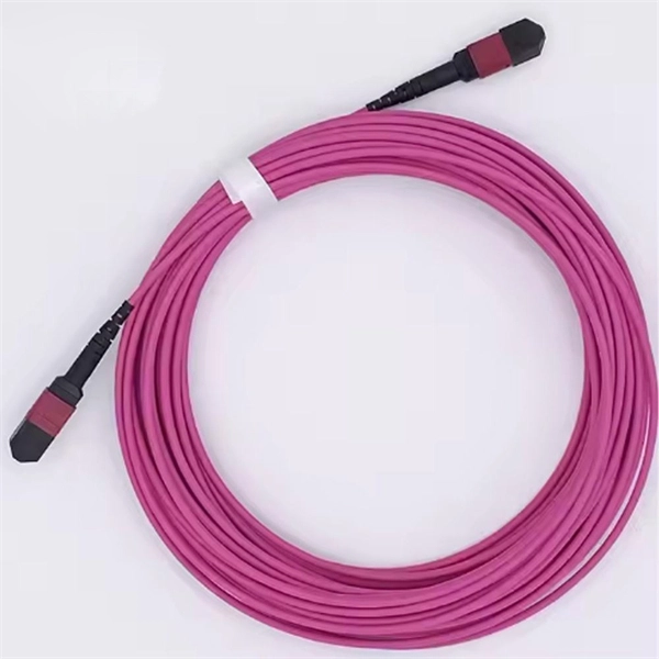
This guide provides a comprehensive engineering perspective on ODFs—beyond the basic “what is an ODF” explanation—covering structural design, fiber management, MPO/MTP integration, and selection criteria for modern high-density deployments. Why ODFs are the Foundation of. This complete guide explores everything you need to know about ODFs — from their structure, types, and key components, to installation best practices and modern design trends. Whether you're building a central office, data center, or FTTx distribution network, understanding the right ODF. In the complex architecture of fiber optic networks, the Optical Distribution Frame (ODF) serves as the linchpin for organizing, protecting, and distributing optical signals. As data centers, enterprises, telecom operators, and smart-building infrastructures deploy increasingly dense fiber links, ODFs provide the structured. An ODF is a central hub in fiber optic networks, crucial for managing and organizing the variety of fiber-optic cables and connections entering a facility such as a telco central office (CO). They provide efficient fiber optic management, connectivity, and protection. What is Optical Distribution Frame An Optical Distribution Frame (ODF) is the central hub of your fiber optic network.
[PDF]

The FLS-140 is the easiest way to identify optical fibers from end to end and locate polished connector endfaces. Its red laser shines through most yellow-jacketed optical fibers to help you pinpoint breaks, bends, faulty connectors, splices and other causes of signal loss. A Visible Fault Identifier (VFI), also referred to as a Visual Fault Locator (VFL), is an essential tool for fiber installation and maintenance technicians. AFL's compact VFI4 injects high-powered red-laser light to provide exceptional brightness and range for locating defects in single-mode and. The B5 Rechargeable Red Light Pen is a professional 650nm visual fault locator designed for fiber optic network maintenance, installation, and troubleshooting. Its advanced rotary automatic lift laser head ensures smooth operation, while the integrated LED lighting improves visibility in low-light. Whether installing or troubleshooting, the Visual Fault Locator (VFL) is an essential tool that quickly and easily locates problem areas in fiber cables. By pinpointing the exact location of fiber damage, technicians can diagnose, troubleshoot, and fix the problem efficiently. The VFL is also used. The state, throughput, and identification of an optical fiber can be easily checked with fiber testers by coupling highly visible laser light into the optical fiber. A high intensity visible red laser beam is precision-coupled.
[PDF]
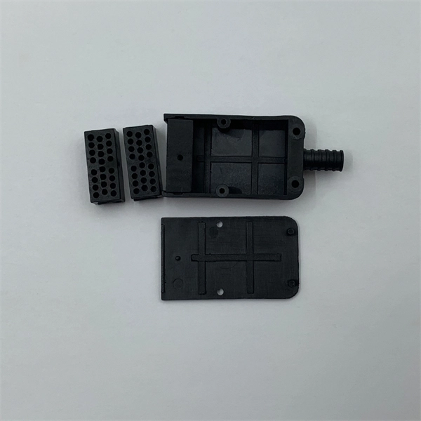
The explosion proof enclosure range has Atex, IECEx, UL Certification s suitable for Zone 1, 2, 21 and 22 Hazardous Areas applications. The highlights: Up to four control elements can be mounted under a single actuator. • Voltmeters and ammeters withstand ambient temperatures as. Atexdelvalle offers world-class explosion-protected solutions guaranteeing highest quality and performance with no compromise. Manufacture custom made Local Control Stations & Distribution Boxes, local control panel boards and stations, explosion protected control units, distribution. An explosion-proof distribution box is a rugged enclosure for hazardous areas, safely delivering power while preventing sparks or heat from igniting flammable surroundings. Its robust construction ensures reliable operation in explosive atmospheres, such as those found in oil, gas, and chemical. Safely conduct, connect and distribute energy in hazardous areas with R. STAHL's terminal boxes. We offer bespoke, custom-made terminal boxes and terminal box combinations, as well as standard products with short delivery times. Our products are certified for installation technologies all over the. That's where explosion-proof distribution boxes become the unsung heroes of industrial safety. These aren't just metal boxes; they're meticulously engineered fortresses designed to contain potential blasts and prevent disaster. Shenhai Explosion-proof Technology Co.
[PDF]
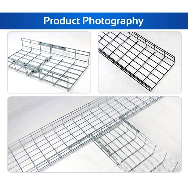
Since our inception in 1992, we have proudly established ourselves as one of Singapore's leading specialists in cable support systems. Our expertise lies in crafting quality metal cable trays, trunkings, and ladders for both commercial and industrial projects. Load Capacity: Ensure the tray can support the weight and volume of your cables. Check manufacturer specifications for load ratings. At Foresight Metal Engineering, we. Organisation and Clutter Reduction - Cable trays excel at organizing cables, reducing clutter, and providing a clean and tidy appearance. This not only simplifies troubleshooting and maintenance but also. Explore a wide range of cable trays from Ferrograte, including perforated, ladder, FRP, and wiremesh trays—ideal for efficient cable management systems. Revolutionise Your Cable Infrastructure with Dynamic Cable Tray Solutions. We offer a range of cable trays which provide structural and mechanical support systems used to support and organise electrical cables and wirings within buildings, industrial facilities, and other installations. They are supplied in straight lengths, but use fittings to make.
[PDF]