
The FLS-140 is the easiest way to identify optical fibers from end to end and locate polished connector endfaces. Its red laser shines through most yellow-jacketed optical fibers to help you pinpoint breaks, bends, faulty connectors, splices and other causes of signal loss. A Visible Fault Identifier (VFI), also referred to as a Visual Fault Locator (VFL), is an essential tool for fiber installation and maintenance technicians. AFL's compact VFI4 injects high-powered red-laser light to provide exceptional brightness and range for locating defects in single-mode and. The B5 Rechargeable Red Light Pen is a professional 650nm visual fault locator designed for fiber optic network maintenance, installation, and troubleshooting. Its advanced rotary automatic lift laser head ensures smooth operation, while the integrated LED lighting improves visibility in low-light. Whether installing or troubleshooting, the Visual Fault Locator (VFL) is an essential tool that quickly and easily locates problem areas in fiber cables. By pinpointing the exact location of fiber damage, technicians can diagnose, troubleshoot, and fix the problem efficiently. The VFL is also used. The state, throughput, and identification of an optical fiber can be easily checked with fiber testers by coupling highly visible laser light into the optical fiber. A high intensity visible red laser beam is precision-coupled.
[PDF]

Free online Snellen-style eye chart for informal vision screening. Calibrate on-screen size, switch chart types, print or download-does not replace a professional eye exam. With instrumentation calibration services from SGS, you can be sure of the highest degree of measurement accuracy, reducing measurement uncertainties and helping maximize profits. Looking for something specific? Loading component. Our calibration services utilize dynamic measurement systems. Check distance vision with on-screen charts-calibrate size, then test at the recommended distance. Adjust the slider until the ruler above measures exactly 10 cm (100 mm). The usual reference distance for Snellen charts is 20 feet (6 meters). For home use, stand at least 10 feet (3 meters) from the. We offer customized calibration procedures specific to the type of monitor and application. Calibration levels range from near background environmental levels to high-dose rate applications. Upon completion of the calibration, you will receive a calibration certificate (e. National Association of.
[PDF]
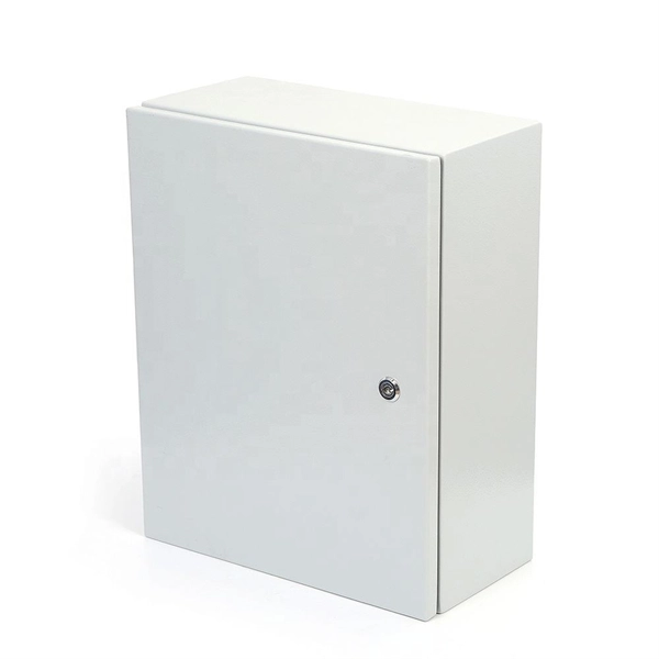
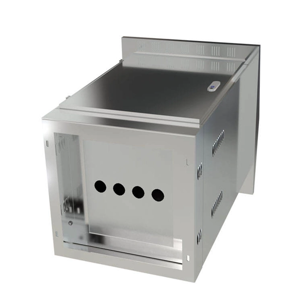
The explosion proof enclosure range has Atex, IECEx, UL Certification s suitable for Zone 1, 2, 21 and 22 Hazardous Areas applications. The highlights: Up to four control elements can be mounted under a single actuator. • Voltmeters and ammeters withstand ambient temperatures as. Atexdelvalle offers world-class explosion-protected solutions guaranteeing highest quality and performance with no compromise. Manufacture custom made Local Control Stations & Distribution Boxes, local control panel boards and stations, explosion protected control units, distribution. An explosion-proof distribution box is a rugged enclosure for hazardous areas, safely delivering power while preventing sparks or heat from igniting flammable surroundings. Its robust construction ensures reliable operation in explosive atmospheres, such as those found in oil, gas, and chemical. Safely conduct, connect and distribute energy in hazardous areas with R. STAHL's terminal boxes. We offer bespoke, custom-made terminal boxes and terminal box combinations, as well as standard products with short delivery times. Our products are certified for installation technologies all over the. That's where explosion-proof distribution boxes become the unsung heroes of industrial safety. These aren't just metal boxes; they're meticulously engineered fortresses designed to contain potential blasts and prevent disaster. Shenhai Explosion-proof Technology Co.
[PDF]
There are two main types of RF attenuators: fixed and variable. Fixed Attenuators: Provide a fixed amount of attenuation, typically designed using discrete or chip resistors. These can be further divided into:. Attenuators are designed to change the magnitude of the input signal seen at the input stage, while presenting a constant impedance on all ranges at the attenuator input. A compensated RC attenuator is required to attenuate all frequencies equally. Without this compensation, HF signal measurements. Let's look at the common types of attenuators Fixed attenuators, as their name suggests, are fixed or unchanging. These are used in applications that don't require changing levels of attenuation or where an occasional replacement of one attenuator with another is acceptable. Say we now add a 6 dB pad between. An RF Attenuator is a two-port passive electronic device designed to reduce (attenuate) the power or amplitude of an RF signal. They can adjust the signal strength by controlling the amount of attenuation, ensuring that the signal reaches the desired level for transmission in a.
[PDF]

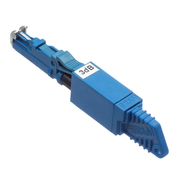
Optical isolators utilize retarders to prevent unwanted reflections, while optical attenuators adjust light intensity by varying polarization alignment. Polarization rotators and variable beam splitters allow controlled redirection of light for applications in optical. There are two primary types of attenuators—variable and fixed. Variable optical attenuators (VOAs) allow for manually adjusting the attenuation of the signal, which is ideal when there is a need to precisely balance signals strength. This is typically achieved by adjusting a screw that changes the. Beamsplitters are optical components used to split incident light at a designated ratio into two separate beams. Additionally, beamsplitters can be used in reverse to combine two different beams into a single one. Beamsplitters are often classified according to their construction: cube or plate. A beam splitter or beamsplitter is an optical device that splits a beam of light into a transmitted and a reflected beam. It is a crucial part of many optical experimental and measurement systems, such as interferometers, also finding widespread application in fibre optic telecommunications. a laser beam) into two (or sometimes more) beams, which may or may not have the same optical power (radiant flux). They are used to divide a beam of light into two or more separate beams. Depending on the design, beam splitters can either reflect a portion of the incoming light and transmit the.
[PDF]
Integrated Power Services (IPS) is your power partner for operating reliability. We repair, rebuild to “like new” condition, and remanufacture electrical equipment. We also supply low- and medium-voltage circuit breakers, switchgear, transformers, and related parts, both new and obsolete. National. From sales to repair to field services, we support reliable energy solutions across clean and traditional power systems. Harnessing energy from clean and traditional sources, we deliver tailored solutions for reliable and efficient power generation systems. Whether it's electromechanical equipment. Integrated Power Supply provides a stable and reliable AC and DC power supplies against all AC mains variations or interruptions. Enhance safety in train operations (by avoiding blanking of signals). It consists of the following modules: The. Independent Power Setup: Critical instruments or instrumentation systems are equipped with dedicated uninterruptible power supplies (UPS). This ensures continuous power during unexpected outages in the main power grid, safeguarding data integrity and preventing equipment shutdown. For instance. At their base level, residential, commercial, and industrial automation complexes must incorporate a wide range of security, safety, and emergency communications systems for insurance requirements and local building codes, and to receive a certificate of occupancy.
[PDF]
This guide provides a comprehensive engineering perspective on ODFs—beyond the basic “what is an ODF” explanation—covering structural design, fiber management, MPO/MTP integration, and selection criteria for modern high-density deployments. Why ODFs are the Foundation of. This complete guide explores everything you need to know about ODFs — from their structure, types, and key components, to installation best practices and modern design trends. Whether you're building a central office, data center, or FTTx distribution network, understanding the right ODF. In the complex architecture of fiber optic networks, the Optical Distribution Frame (ODF) serves as the linchpin for organizing, protecting, and distributing optical signals. As data centers, enterprises, telecom operators, and smart-building infrastructures deploy increasingly dense fiber links, ODFs provide the structured. An ODF is a central hub in fiber optic networks, crucial for managing and organizing the variety of fiber-optic cables and connections entering a facility such as a telco central office (CO). They provide efficient fiber optic management, connectivity, and protection. What is Optical Distribution Frame An Optical Distribution Frame (ODF) is the central hub of your fiber optic network.
[PDF]
A beam splitter or beamsplitter is an optical device that splits a beam of light into a transmitted and a reflected beam. It is a crucial part of many optical experimental and measurement systems, such as interferometers, also finding widespread application in fibre optic telecommunications. DesignsIn its most common form, a cube, a beam splitter is made from two triangular glass which are glued together at their base using polyester,, or urethane-based adhesives. (Before these synthetic,. Beam splitters are sometimes used to recombine beams of light, as in a. In this case there are two incoming beams, and potentially two outgoing beams. But the amplitudes. For beam splitters with two incoming beams, using a classical, lossless beam splitter with Ea and Eb each incident at one of the inputs, the two output fields Ec and Ed are linearly related to the inputs thro.
[PDF]

In this guide, you will learn how to interpret network diagrams like a pro, from symbols and scope to segmentation, dependencies, troubleshooting, and security clues. A rack elevation diagram is a visual representation of the equipment and components contained within a rack in a data center or server room. It provides a clear overview of the physical layout of the rack, including the placement and positioning of servers, switches, storage devices, and other. Learn how to read and interpret network diagrams effectively to troubleshoot, validate security, and plan network changes with confidence. Have you ever opened a network diagram and felt like you were staring at a subway map with no station names? That is a common problem, even for experienced IT. Network cabinet cabling describes the structured connection and arrangement of all IT components in a server rack. The aim is a secure, maintainable and scalable operation of the network environment. The amount. A standard operating procedure, or SOP, is a set of step-by-step instructions compiled by an organization to help workers carry out complex routine operations. Work instructions should be very detailed on "how" to accomplish a specific job, task or assignment. It helps teams understand network architecture, data flow, and dependencies, making it easier to design infrastructure, troubleshoot issues, and plan.
[PDF]
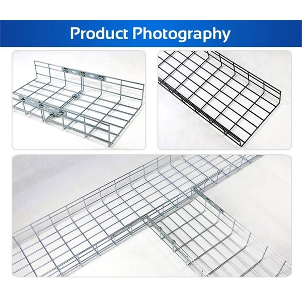
Since our inception in 1992, we have proudly established ourselves as one of Singapore's leading specialists in cable support systems. Our expertise lies in crafting quality metal cable trays, trunkings, and ladders for both commercial and industrial projects. Load Capacity: Ensure the tray can support the weight and volume of your cables. Check manufacturer specifications for load ratings. At Foresight Metal Engineering, we. Organisation and Clutter Reduction - Cable trays excel at organizing cables, reducing clutter, and providing a clean and tidy appearance. This not only simplifies troubleshooting and maintenance but also. Explore a wide range of cable trays from Ferrograte, including perforated, ladder, FRP, and wiremesh trays—ideal for efficient cable management systems. Revolutionise Your Cable Infrastructure with Dynamic Cable Tray Solutions. We offer a range of cable trays which provide structural and mechanical support systems used to support and organise electrical cables and wirings within buildings, industrial facilities, and other installations. They are supplied in straight lengths, but use fittings to make.
[PDF]
