An optical transport network (OTN) is a digital wrapper that encapsulates frames of data, to allow multiple data sources to be sent on the same channel. This creates an optical virtual private network for each client signal. ITU-T defines an optical transport network as a set of optical network elements (ONE) connected by optical fiber links, able to provide functionality of transport, multiplexing, swit. EquipmentAt a very high level, the typical signals processed by OTN equipment at the Optical Channel layer are: • SONET/SDH• Ethernet/FibreChannel• Packets. • - Details of all OTN areas including breakdown of the full frame Anritsu Poster - Details of all OTN areas including breakdown of the full frame at the Wayback Machine (archived 2014-05-17)•.
[PDF]

Optical amplifiers work differently. They amplify the light directly, with no conversions. This process is faster, more efficient, and keeps the signal clearer. Using optical amplifiers helps reduce signal distortion, lowers system costs, and supports long-distance communication. The most common types include: Erbium Doped Fiber Amplifiers (EDFA): EDFAs are the most commonly used type of optical amplifier in telecommunications. They play a vital role in modern optical communication systems, enabling the transmission of high-speed data over long-haul networks. An optical amplifier is a device that boosts the strength of an optical signal. 2dB per kilometer for 1. This means that over a distance of 100km, a signal can lose around 20dB. This principle dictates that a photon can interact with an atom already in an excited energy state, forcing the excited atom to immediately release its stored energy as a second photon. It does this without changing the light into an electrical signal. In the past, systems used repeaters to fix weak signals. These repeaters turned light into electricity, boosted the signal, and then. The SPIE Digital Library offers a comprehensive range of content on optical amplifiers, reflecting their significance in modern photonics and telecommunications. The library includes a variety of peer-reviewed papers, conference proceedings, and technical articles that delve into the fundamental.
[PDF]

Explore 74 top manufacturers and suppliers of Optical Testing Instruments in our comprehensive photonics buyers' guide. An optical testing instrument is a device or system used to evaluate and measure the performance, quality, and characteristics of optical components. Source Photonics, founded in 1988 and based in Los Angeles, California, is a technology company that specializes in optical transceivers and data connectivity solutions. The company provides a wide range of products tailored for data centers, broadband, and optical transmission, serving. CACI designs and manufactures optical communications terminals for all of the major orbits in which our customer missions operate. These bespoke solutions are being manufactured in Orlando at CACI's space manufacturing and testing facility, which opened in June 2022. The facility is dedicated to. Manufacturer of standard and custom opticaltestequipment including microscopes, pocket comparators, disc gages, grids, scales, strips, slits, and micrometers. Suitable for optical, gaging, imaging, and calibration applications. Serves aviation industry. Lapmaster Wolters is estimated to have. Optical transceivers are devices that convert electrical signals into optical signals for transmission and reception. They are primarily used in communication systems that employ optical fiber cables, serving the purpose of signal conversion between the transmitting and receiving ends.
[PDF]

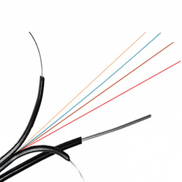
Optical Fiber Communication (OFC) revolutionizes modern telecommunications, enabling rapid data transfer across long distances with minimal signal loss. This comprehensive review explores OFC's historical evolution, core principles, components, and versatile applications. It traces OFC's. Additionally, optical fiber is lightweight and less susceptible to noise (no electromagnetic induction). Optical fiber consists of a cylindrical core that propagates light and a concentric cladding that surrounds it. The cladding's refractive index is slightly smaller than that of the core, which. Fibre optics and optical communications is the use of thin strands of glass for sending information encoded into light over long distances. Total internal reflection prevents light inserted into one end of the fibre from escaping through the sides. Keywords: Optical fibers, communication systems, data. Figure 1: Illustration of the inverse-square law of light intensity – the light's intensity diminishes with the square of the distance, which free-space optical signals must overcome (leading to very weak reception at long range) Figure 1 illustrates how light intensity decreases as distance.
[PDF]

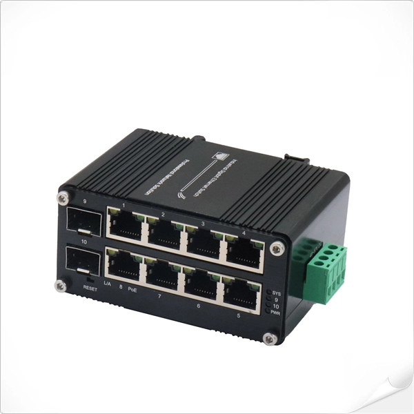
Run the display transceiver [ interface interface-type interface-number | slot slot-id ] [ verbose ] command to view information about the optical module on a specified interface. In optical communication equipment, an optical module (Optical Module) contains several types of semiconductor chips that work together to complete the transmission and processing of optical signals. These chips typically include laser chips, photodetector chips, driver chips, transimpedance. When the optical module on an interface is faulty, you can run the display commands to view information about the optical module. Today, we will deeply analyze the four mainstream models of 100G QSFP28 dual-fiber optical modules: QSFP28-100G-SR4, QSFP28-100G-LR4, QSFP28-100G-ER4 and. The following uses the Moduletek SFP-10G-LR module connected to a Huawei S6700 switch as an example to introduce how to read information of the connected optical module on a Huawei switch. Figure 1 Schematic Diagram of Optical Module Connected to Switch 1. Optical Module Status Check Run the. Upgrade to 100G or 400G optics and save. Cisco Transceiver Modules - Learn product details such as features and benefits, as well as hardware and software specifications. Network administrators have a major challenge determining the right Cisco SFP modules, understanding complex model numbers that directly affect network performance and stability.
[PDF]

An optical transceiver module, often simply called an optical module, acts as a signal conversion interface in fiber optic networks. It transforms high volumes of electrical signals into optical signals for transmission over fiber cables, or reverses the process at the receiving. In the world of fiber optic communications, optical transceiver modules play a pivotal role as interfaces that convert electrical signals to optical signals and vice versa. If you're dealing with data centers, telecommunications, or AI networking, grasping the key parameters of an optical. Optical transceivers are efficient in changing signals. These modules have many parts, each with a specific functions: Takes in electrical signals to change them. Powers lasers or LEDs to send light signals. Combines many light signals into one for. An optical transceiver, a crucial device utilized in optical communication, is an optoelectronic element, allowing the interconversion of optical and electrical signals during the information transmission. Acting as the "heart" of fiber-optic networks, these modules—ranging. This comprehensive guide breaks down the internal structure, core components (TOSA, ROSA, lasers), and operational mechanisms of SFP optical modules, enriched with technical insights and real-world applications.
[PDF]

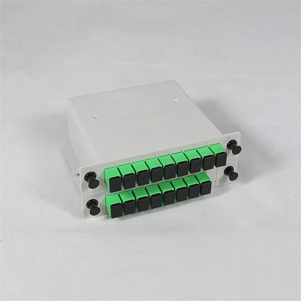
Here's a step-by-step guide to help you set up your fiber distribution box seamlessly: Before installing the fiber distribution box, ensure that your optical cables are properly prepared for connection. The optical fiber distribution box allows people to easily access the optical fibers in the box, and can well protect the optical fibers. In addition, the drawer structure also facilitates high-density wiring and good cable management. However, because optical fibers are fragile and can be easily. Keeping this page as a placeholder for now. Have any questions? Talk with us directly using LiveChat. Fix the rack to the ground with expansion bolts. Top installation: Dimensions of four connection holes on the top according to the. This instruction describes the installation of the Fiber Distribution Frame (FDF) manufactured by Corning Optical Communications. To order accessories that are purchased separately, contact Corning Optical Communications customer care for assistance. Read and understand this procedure (as well as. Optical fiber distribution frame is the wiring connection equipment between optical cable and optical communication equipment or between optical communication equipment. Distribution boxes are especially essential for FTTH networks, where they enable the efficient connection and management of optical fibers from a central.
[PDF]

The wavelength of the 40G QSFP+ SR4 optical module is 4x850nm, while the 40G QSFP+ LR4 optical module adopts CWDM coarse wavelength division multiplexing technology, with four wavelengths of 1271nm, 1291nm, 1311nm, and 1331nm. The fiber type and connector are different. 40GBASE-ER4 is a long-reach 40GbE optical standard that delivers 40Gbps transmission over single-mode fiber up to 40km using QSFP+ transceiver. It achieves this reach by multiplexing four CWDM optical lanes into a duplex LC fiber interface, allowing long-distance connectivity without requiring. While 100G and 400G technologies continue to advance, 40G QSFP+ optical modules remain a mainstream, cost-effective solution for upgrading small to medium-sized data centers. It is commonly deployed in data centers, enterprise backbone networks, and metropolitan area networks where stable, high-speed transmission over extended distances is. In the deployment of 40G networks, the 40G QSFP+ optical module is one of the most widely used, defined by IEEE 802. The two basic interface specifications for QSFP+ optical modules are 40G BASE-SR4 and 40G BASE-LR4. In this blog, ETU-LINK will talk about. The QSFP+ module is designed for use in 40GBASE Ethernet throughput up to 10km, 30km or 40km over single mode fiber (SMF) using a wavelength of 1310nm via duplex LC connectors. This transceiver is compliant with QSFP+ MSA and IEEE 802. Digital diagnostics functions are also available.
[PDF]
Built with GF's advanced silicon photonics technology, the SCALE CPO solution utilizes both coarse and dense wavelength-division multiplexing (CWDM, DWDM) for bi-directional data transmission over each optical fiber for significant improvements in bandwidth density and system. Built with GF's advanced silicon photonics technology, the SCALE CPO solution utilizes both coarse and dense wavelength-division multiplexing (CWDM, DWDM) for bi-directional data transmission over each optical fiber for significant improvements in bandwidth density and system. MALTA, N., May 04, 2026 (GLOBE NEWSWIRE) -- GlobalFoundries (Nasdaq: GFS) (GF) today announced the introduction of its SCALE™ optical module solution for co-packaged optics (CPO). GF's SCALE solution, or Silicon photonics Co-packaged Advanced Light Engine solution, is the industry's first Optical. MALTA, N. 9, 2024: IBM (NYSE: IBM) has unveiled breakthrough research in optics. These pressures are driving renewed momentum behind co-packaged optics (CPO). According to LightCounting, sales of lasers and photonic integrated circuits for optical transceivers are expected to grow from $2. 9B by 2029, fueled largely by AI data centers.
[PDF]
The Intellinet Network Solutions 10 Gigabit Fiber SFP+ Optical Transceiver Module (model 507479) is fully hot-pluggable, and that allows you to install the module without rebooting your network switch for uninterrupted network traffic. Intellinet Network Solutions 10GBase-LR Fiber SFP+ Optical Transceiver Module, model 507479, is the right choice when it comes to connecting two buildings at 10 GbE speeds with single mode fiber. That's a 10 Gbps connection up to a distance of 10 km (or 6.2 miles). The transceiver comes in a mini-GBIC form factor, making it ideal for environments that require many fiber connections by taking up less space in your cabinet and/or computer room. Compatibility in your network is everything, and the Intellinet Network Solutions SFP+ Transceiver Module (model 507479) delivers. Use it with any Intellinet Network Solutions SFP+ equipped network switch or any other MSA compliant SFP+ enabled switch. And since the Intellinet Network Solutions SFP+ transceiver module is set to broadcast the vendor. The Intellinet Network Solutions 10 Gigabit Fiber SFP+ Optical Transceiver Module (model 507479) supports standard digital diagnostics monitoring (DDM) functions, also known as digital optical monitoring (DOM). This gives the user the ability to monitor parameters of the SFP, such as optical output power, optical input power, temperature, laser bia.
[PDF]
Cambodia Fibre Optic Communication Networks Co., Ltd (CFOCN) has requested the Ministry of Public Works and Transport (MPWT) for approval to undertake a project involving the drilling and installation of new fibre optic cables across Cambodia's nine major provinces. This request was discussed during a meeting. Established since 2022, and obtained a license from Telecommunication Regulator of Cambodia (TRC) Who We Are? Established in 2022, and obtained a license from the Telecommunication Regulator of Cambodia (TRC). – Cambodia Licensed Provider for Operation and Provision of Telecommunications Cable. Telcotech is Cambodia's trusted choice of Telecommunication Infrastructure and Associated Services Provider. With a 30,000-kilometer-long. The project company comprises investment of two fiber optic telecommunication networks which are the undersea fiber optic cable Asia-Africa-Europe 1 (AAE-1) and the land cable network (the 'Project'), as detailed in the following report. The project will be developed by (Cambodia) Fiber Optic. Phnom Penh (FN), Aug. 14 – Telcotech is one of the market leaders for infrastructure in Cambodia, subsea cable and also connectivity in the region, announced the cooperation with Huawei building Cambodia's first nationwide next generation transport network. It is understood that the network will.
[PDF]

A ceramic sleeve is a small, cylindrical element employing zirconia, which is a strong, low thermal expanding ceramic used in a fiber optic system to locally align and hold the interface between the fibers or connectors. It ensures precise alignment. Known for their high-temperature resistance, wear resistance, and chemical stability, ceramic sleeves have become a key element in applications spanning communications, electronics, automotive, aerospace, and industrial systems. The industry is developing in a diversified manner, connecting raw. Most of the ferrules used in optical connectors are made of ceramic (Zirconia) material due to some of the desirable properties they possess. Kyocera's extrusion molding process creates ferrules with excellent coaxiality, and our precision machining ensures excellent concentricity with precise. Alignment sleeves are the primary mechanical reference inside a fiber optic adapter. Their role is to constrain lateral offset, angular deviation, and axial separation between mating ferrules, directly determining insertion loss and return loss stability. Historically, both ceramic and phosphor. The global market for ceramic sleeves is experiencing robust growth, projected to reach an estimated $287 million by 2025. This expansion is fueled by an impressive CAGR of 20. 5% during the study period. The primary drivers for this surge are the increasing demand for high-performance optical.
[PDF]
An optical time-domain reflectometer (OTDR) is an optoelectronic instrument used to characterize an optical fiber. It is the optical equivalent of an electronic time domain reflectometer which measures the impedance of the cable or transmission line under test. An OTDR injects a series of optical pulses into the fiber under test and extracts, from the same end of the fiber, light that is scatter. Reliability and quality of OTDR equipmentThe reliability and quality of an OTDR is based on its accuracy, measurement range, ability to resolve and. The common types of OTDR-like test equipment are: 1. Full-feature OTDR: 2. Hand-held OTDR and Fiber break locator: 3. RTU in RFTSs:. In the late 1990s, OTDR industry representatives and the OTDR user community developed a unique data format to store and analyze OTDR fiber data. This data was based on the specifications in GR-196, G.
[PDF]
Please select a category, brand, and model to find a type-approved device. Results will be displayed here after search. You can now apply and manage your RSB services online. Start today! The RSB Standards Store has a wide range of Standards covering various sectors and industries. Need help with any of your other applications? Apply for Zamukana Ubuziranenge and get assistance from our staff. Increase the. An LPO (Linear Pluggable Optics) solution offers considerable power savings for optical interconnect by removing the digital signal processing (DSP) function from the pluggable optical module. The idea is simple: instead of a DSP (digital signal processor) inside the module – replacing it with transimpedance amplifier (TIA) and a driver chip with high linearity and EQ capability – LPO shifts signal processing into. LPO (Linear-drive Pluggable Optics) is a transceiver packaging technology. It utilizes specialized components, including ASIC substrates, ASIC. In response, several solutions such as Linear Receive Optics (LRO), Linear Pluggable Optics (LPO) and Co-Packaged Optics (CPO) have been proposed. 1 shows the typical block diagram of a pluggable transceiver consisting of on-board lasers, optics, a Photonics die housing the modulator.
[PDF]

Precast concrete trench systems provide protection and easy access to power, communication, fiber optic, control, and signal wires and cables. Engineered precast trench is used in the power, utility, and transportation industries and can also be used in conjunction with catch basins, inlets, and. Completing Outside Cable Plant Installation. Underground cables are pulled in conduit that is buried underground, usually 1-1. 2 meters (3-4 feet) deep to reduce the likelihood of accidentally being dug up. In extreme cold climates, cables may need to be buried at greater depths where there. THE SOLID APPROACH TO TRENCHING. Made of a unique, patented. Trenwa is the original manufacturer of precast concrete trench and offers the broadest line of proven trench systems. Trusted by Industry Leaders: Trenwa has been a go-to partner for North American infrastructure projects for over for over 60 years. Request a quote today to see how our products can. Waskey's Precast Cable Trench System offers a durable, customizable solution for protecting and organizing critical infrastructure. If you need any help, be sure to reach out. Precast Concrete Trench for underground utility purposes. Primarily used for enclosure of electrical, communication, power cables, and piping.
[PDF]

