A typical fiber optic splice enclosure consists of several key components that work together to protect and organize the fiber splices. Standard enclosures contain: 1) Housing, 2) Cable fixation clamps, 3) Splice trays, 4) Sealing system. A splice box (also known as splice distributor) is a housing in which fiber optic cables begin or end. Fiber optics are fanned out in splice boxes that are situated at the end of fiber optic transmission paths. Optical cable joint box The optical cable joint box permanently connects two optical cables together and has a joint part for protecting components. The optical cable connection part, that is, the optical cable joint, is the part where the. An optical cable split fiber box, also known as a fiber distribution box or fiber optic splice closure, is a device used to terminate, splice, and distribute optical fibers. In this response, we will focus on the. This guide optimizes the original text by delving deeper into the three pillars of fiber network longevity: the impact of splicing technology, the strategic selection of splice boxes, and the essential maintenance protocols needed to ensure sustained, high-speed functionality. Fibre optic cables are manufactured in standardized lengths –.
[PDF]
The principle of gap-loss is used in optical attenuators to reduce the optical power level by inserting the device in the fiber path using an inline configuration. Gap-loss attenuators are used to prevent the saturation of the receiver and are placed close to the transmitter. The basic types of optical attenuators are fixed, step-wise variable, and continuously variable. The attenuator circuit will allow a known source of power to be reduced by a predetermined factor, which is usually expressed as decibels. In fiber systems, attenuation is specified in dB (a ratio), while optical power is often given in dBm (absolute power referenced to 1 mW). If a transmitter outputs +3 dBm and. If you are still looking to reduce the signal power of optical fiber links, Optical Attenuators are undoubtedly a good choice and can bring you a good solution. Because the signal power of the optical fiber link is too high, it will cause abnormalities in the optical fiber network, so it is. A Variable Optical Attenuator (VOA) is a controllable device used to reduce the optical power traveling through a fiber or free-space optical path. Unlike a fixed attenuator, which imposes a constant loss, a VOA allows the loss to be adjusted from nearly zero up to tens of decibels. Understanding their principles is essential for their effective application. Optical attenuators work by absorbing or reflecting a portion of the optical signal, thus reducing its.
[PDF]

STM-1 (Optical / Electrical), E1 and Ethernet Multi-Service SDH Transmission Unit is a modular platform unit with two 155. 52Mbps optical / electrical interfaces, which may be used in a point-to-point, chain or ring application to provide an ultra-compact, cost effective and flexible. STM-1 Mux is a cost-effective, compact (only 1U high), SDH (Synchronous Digital Hierarchy) multiplexer that is designed for applications in metro and access networks for efficient transport of traditional TDM and emerging data traffic. It provides 63 E1 TDM interfaces in only 1U standard 19". The LentronicsTM TN1U SDH Multiplxer delivers powerful optical networking solutions for critical communications applications. With a wide range of tributary interface units, the TN1U provides both transport and access capabilities for voice, data, IP/Ethernet Wide Area Network (WAN), video and. Valiant's offers STM-1 63 E1 (Optical / Electrical), Add-Drop SDH Multiplexer unit is a modular platform unit with two 155. R-STM-1E can be deployed in access nodes as a terminal multiplexer (TM) or an add & drop multiplexer (ADM). It enables expansion of the local loop up to 100 km / 62 miles. Note: 1643 AM STM-1 (Aggregate and tributary) or STM-4 optical access is via an SC-type connector. Adaptors FC and ST are also supplied. 1643 AMS: All optical interfaces are available as SFPs (Small Form-Factor Pluggable Optics) for STM-1 transmission only. Note that the 1643 AM supports S1.
[PDF]
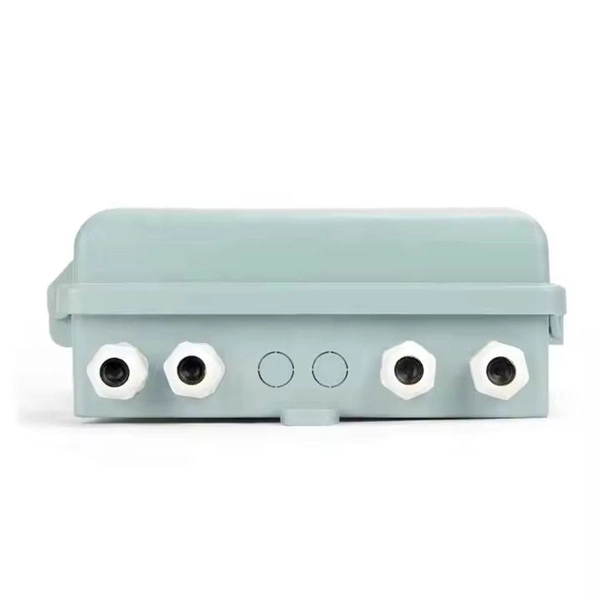
An optical junction box is a vital component in fiber optic networks. It serves as a termination point for fiber optic cables, providing protection and distribution of the optical fibers while ensuring efficient signal transmission. Optical cable junction boxes play a crucial role in connecting and protecting optical fibers, directly influencing the quality and lifespan of optical cable routes. As the demand for high-speed internet and reliable telecommunications increases, the. What is an optical cable splice box Optical cable splice box is a popular name, its scientific name is optical cable splicing box, also known as optical cable splicing package, optical cable splicing package and gun barrel. It belongs to the mechanical pressure sealing joint system and is a splice. --- Optical Fibre Junction Boxes are critical components in the realm of telecommunications, serving as the interfacing point for optical networks.
[PDF]
will introduce major upgrades to its Multi-Rail technology platform at ECOC 2025, targeting hyperscale optical transport with new efficiency, scale, and performance enhancements. Coherent Corp. SAXONBURG, PA, September 26, 2025 (GLOBE NEWSWIRE) – Coherent Corp. At the heart of the. SAXONBURG, Pa. At the heart of the. Simultaneously, coherent technology has emerged as the prevailing solution for Data Center Interconnection (DCI) applications, covering distances of 80~120km in the field of data communication. These evolving applications introduce new demands for coherent optical transceiver systems, steering the. Coherent optical module refers to a typically hot-pluggable coherent optical transceiver that uses coherent modulation (BPSK / QPSK / QAM) rather than amplitude modulation (RZ/ NRZ / PAM4) and is typically used in high-bandwidth data communications applications. Optical modules typically have an.
[PDF]
In fiber optic circuit technology an optical fiber link is used for transferring digital or analogue data in the form light frequency through a cable which has a highly reflective central core. Internally, the optical fiber.
[PDF]
1. Scope: This quality procedure is made to enumerate to perform the fiber optic cable installation, termination and testing work in SAOMPP Project. 2. Purpose: The purpose of this quality procedure is to establi.
[PDF]

Summary : Fiber optic cables use light pulses to transmit data through ultra-thin glass or plastic strands, offering high-speed, long-distance communication. These cables rely on components like the core, cladding, strength member, coating, and outer jacket. These systems transmit digital information as rapid pulses of light through incredibly thin strands of pure glass, rather than as electrical current through metal wires. Multimode fibres operate primarily at 850 nm and sometimes at 1300 nm slightly different speeds. This is how optical prisms work Note: Forward Error Correction (FEC) is used to maximise link length for a given bit error. Optical fiber communication systems have become the cornerstone of modern telecommunications over the past four decades. As the demand for high-speed, high-capacity data transmission continues to grow exponentially, these systems have become increasingly essential. Harnessing the power of light. This is the FOA's Online Guide To Fiber Optics, Fiber Broadband & Premises Cabling. They operate on the principle of total. Designing a fiber optic network is like planning a city's road system, it needs to be efficient, reliable, and built to handle both current and future traffic. This fundamental aspect of modern infrastructure connects our homes, businesses, and communities to the digital world. Whether you're new.
[PDF]

Optical cable lines lightning protection and strong current protection are achieved by avoiding, guiding or discharging them underground to prevent lightning and strong current from causing damage to the optical cable lines themselves, communication equipment and personnel. Since the lightning. Fiber optic cables have good protection performance, and the metal components of cable's insulation value is so high that lightning current can not enter the cable easily. However, because fiber optic cable has strengthened core, especially the direct-buried fiber optic cable has armoring layer. rocess approved by the American National Standards Institute. This process brings together volunteers representing varied viewpoints and i terests to achieve consensus on fire and other safety issues. While the NFPA administers the process and establishes rules to promote fairness in the. The Lightning Protection Institute is a nationwide not-for-profit organization founded in 1955 to promote lightning protection education, awareness, and safety. The lightning protection industry began in the United States when Benjamin Franklin postulated that lightning was electricity, and a metal. Defines lightning parameters (current waveform, peak values, charge transfer), threat classification, and damage/loss categories. Provides the risk assessment methodology.
[PDF]

This practical file details experiments conducted in Optical Fiber Communication, covering modulation techniques, system components, and performance analysis. An optical fiber is a glass or plastic fiber designed to guide light along its length, widely used in fiber-optic communication, which permits transmission over longer distances and at higher data rates than other forms of communications. Fiber-optic communication is a method of transmitting. Availability of plastic optical fiber (POF) The plastic optical fiber used in some of these experiments is available for science distributors. It is a 1000micron (1mm) POF available from several suppliers. FOA has samples available at no cost for teachers at schools in the US. Key experiments include amplitude modulation, frequency modulation, and pulse width modulation, aimed at understanding fiber optic systems. This document summarizes 10 experiments on optical fiber communication: 1. Studying a 650mm fiber optic analog link and the relationship between input and received signals. Optical fiber communication Laboratory Optical fiber communication Laboratory List of Experiments: 1. To set up a analog optical fiber link 2. To measure the characteristics of LED and LASER 5. Tech curriculum designed to provide a comprehensive understanding of optical fiber communication systems. This lab offers an immersive, web-based simulator that enables you to explore and experiment with key concepts in optical.
[PDF]

What is the main cause of attenuation in fiber? Attenuation in fiber mostly happens from absorption and scattering. The fiber material takes in some light as it moves. Both of these things make the signal weaker as it goes through the. Optical Signal Attenuation is the single greatest factor limiting the distance and performance of your network. Understanding it is crucial for anyone involved in data centers, telecommunications, or enterprise networking. This guide will demystify signal loss, explore its causes, and show you how. Optical fibers are a key component in modern communication systems, carrying signals over long distances. However, even the most advanced optical fiber suffers from attenuation, which is the loss of signal power as it travels along the fiber. Understanding the causes of signal loss and implementing mitigation strategies is essential for maintaining network efficiency. From infrastructure planners to telecom engineers. Optical fiber technology enables rapid data transmission over vast distances by guiding light signals through thin strands of glass. Losses can be introduced by various means such as intrinsic material absorption, scattering, bending, connector loss and more.
[PDF]

Multi-mode fiber optic patch cords utilize a larger core size, typically around 50-100 microns, allowing them to carry multiple modes of light. This design enables the transmission of data over relatively short distances with high bandwidth capabilities. A fiber-optic patch cord is a fiber-optic cable capped at each end with connectors that allow it to be rapidly and conveniently connected to telecommunication equipment. This is known as interconnect-style cabling. A fiber-optic patch cord is constructed from a core with a high refractive. These short fiber optic cords connect transceivers, switches, patch panels, and servers. Without them, even the best optical modules and switches cannot deliver performance. As data rates increase from 10G → 100G → 400G → 800G, patch cables must handle more bandwidth, more density, and stricter. Fiber optic patch cords, also known as fiber optic patch cables or fiber jumpers, are indispensable components in modern optical networks. They act as the critical link for interconnecting devices like optical switches, servers, and distribution frames. Understanding the various technical. Fiber patch cables, also called fiber-optic patch cords, are cables typically containing one or two optical fibers, which are equipped with standardized fiber connectors on both ends. The function of the fiber patch cord.
[PDF]
Underground fiber optic cable carries the vast majority of the world's internet traffic, phone calls, and digital data. These cables are buried beneath streets, sidewalks, and rural land to connect homes, businesses, data centers, military installations, and city infrastructure. While the glass. Underground fiber optic cable is designed for direct burial or conduit installation and is widely used in FTTH networks, backbone infrastructure, and industrial communication systems. This guide explains underground fiber optic cable types, installation methods, burial depth, and practical. One of the key components driving this connectivity is underground fiber optic cable. It has been increasingly used in telecommunications networks around the world. Introduction of The Buried Fiber Optic Cable Fiber optic cables have revolutionized the way we transmit data, offering unparalleled speeds and reliability.
[PDF]

Optical fiber technology has revolutionized the way we communicate, enabling fast and reliable data transmission over long distances. In this article, we will explore the different types of optical fibers used in communication systems and their applications. Fiber Optics or Optical Fiber is a technology that transmits data as a light pulse along a glass or plastic fiber. An Optical Fiber is a cylindrical fiber of glass that is hair-thin in size or any transparent dielectric medium. The fiber which is used for optical communication is waveguides made of. Optical fibers are the backbone of modern communication. They transmit light signals over long distances with minimal loss. Let's break down their classification in a simple and engaging way: 1. The less signal damage metal wires can cause, the better for optical fiber connection. Total internal reflection (critical angle, using Snell's law). Higher bandwidth (extremely high data transfer rate). Less signal degradation. Less costly per meter. Lighter and thinner then copper wire. The light is a form of carrier wave that is modulated to carry information. The cladding's refractive index is slightly smaller than that of the core, which confines light within the core and propagates by repeated total reflection at the boundary with the.
[PDF]
G652D optical fiber has been in use for almost 30 years in optical communication. There are two types of optical fibers: single-mode and multi-mode. These modes in optical fibers refer to the pattern of light traveling inside them. G652D is a. G652D optical fiber has been in use for almost 30 years in optical communication. There are two types of optical fibers: single-mode and multi-mode. These modes in optical fibers refer to the pattern of light traveling inside them. G652D is asingle-mode optical fiber; only one light pattern can travel inside it. It has been a favourite because of i. Advantages of the fiber optic cable are as follows: 1. Polarisation Modal Dispersion (PMD) is when two polarisations of light travel at different speeds, causing the spreading of the signal. This spreading reduces the signal strength. The G652D fiber offers a higher PMD performance compared to G652C. 2. Water peaks are where the water molecules are. Theadvantages of optical fibertechnology have offered many applications for G652D fibers. ITU-T G652D single-mode fibers are primarily used in networking and communication. You can use the G652D fibers for both short- and long-range networking applications. For example, you can use these fibers for LAN, MAN, and access networks. TheseG652D fibers h.
[PDF]