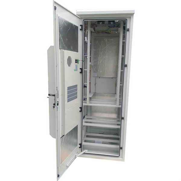
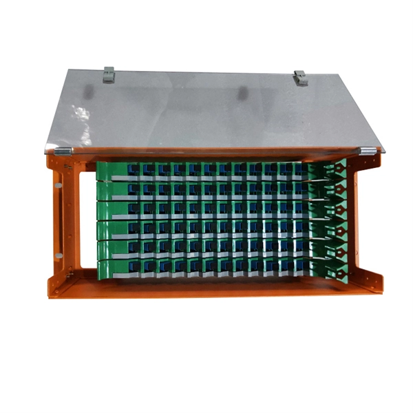
In network cabling, outdoor connections generally use fiber optic cables. When these optical fibers are installed or laid out, a Fiber Termination Box, or FTB, is used to distribute and protect the optical fiber link.
[PDF]
In network cabling, outdoor connections generally use fiber optic cables. When these optical fibers are installed or laid out, a Fiber Termination Box, or FTB, is used to distribute and protect the optical fiber link.
[PDF]
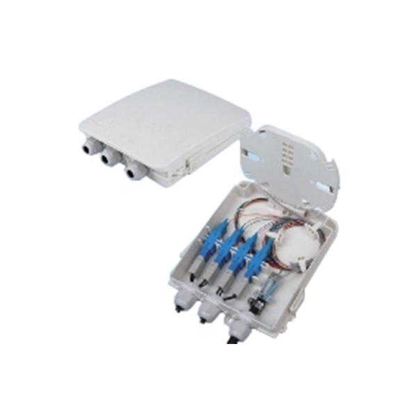
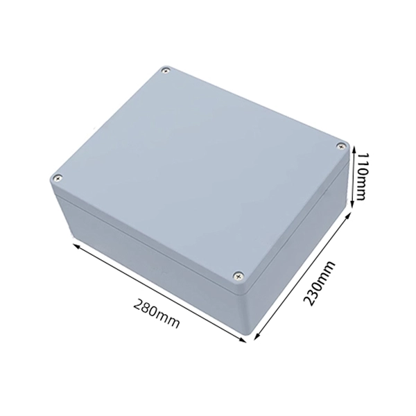
The 2 port surface mount fiber enclosure serves as termination point designed to joint drop cable and pigtail in home or office for wall mout or suface mount installation. It fully supports mechanical/fusion splicing, termination, and cable mangement within a single, compact indoor unit. The. The fiber panel box provides superior protection as the main function of the panel is to fix the module, protect the cable at the information outlet, and play a role similar to a screen. The fiber optic terminal junction Box solid in construction,with porcelain white finish. The fiber splicing, splitting, distribution can be done in this box, and meanwhile it provides solid protection and management for the FTTx network building. Modern telecommunications depend on 2 core connection box as basic building blocks for fast data transfer over great distances. These devices and systems use light to transport data and provide better dependability and bandwidth than conventional copper connections. They are indispensable in many. The 2 Cores Fiber Distribution Box (FDB-102A-1) IP-55 SC Connector PLC Splitter is a compact and rugged outdoor enclosure designed to provide a safe and secure environment for fiber optic cables and splices. Copyright 2024 FOCC All trademarks, products, and company names mentioned are the property. Product added! Browse Wishlist Max. Inlet Cable Diameter Max.
[PDF]
This diagram shows how the RJ45 cable is connected to the PoE switch, allowing it to power devices such as IP phones and cameras. In this article, we will explore the wiring diagram for a PoE switch, which provides a visual representation of how the switch connects to various devices. Each device is represented by a. Do you want to set up a new computer network in your home or office? Chances are, you'll need a Poe switch wiring diagram. Not only do these diagrams provide all the information you need to install a network, but they also help make the process easier and more efficient. For those who don't know. A PoE Switch, also known as Power over Ethernet Switch, is a network device that allows users to power and connect devices such as IP cameras, VoIP phones, and wireless access points. In essence, a PoE Switch can be described as regular switch with added ability of Power over Ethernet which allows. PoE technology enables the transmission of both data and power over a single ethernet cable, simplifying network setups and eliminating the need for additional power sources. This is particularly useful in scenarios where devices like IP cameras, wireless access points, or VoIP phones need to be. Here, you can see the details, Keep the copper strips towards your face and count the pin number or pin position from left to right. The T568B also has a total of eight pins and sight different colors.
[PDF]
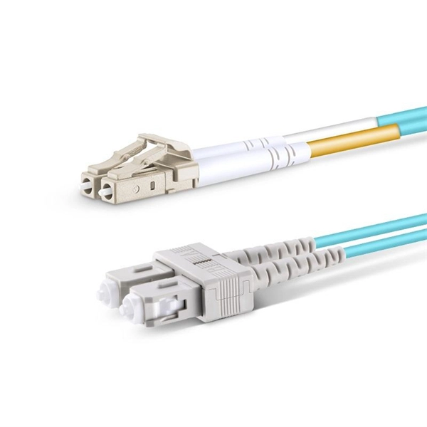
This article will guide you through the process of troubleshooting fiber optic connections, with a focus on ensuring proper TX and RX alignment and how to correctly switch patch cables to resolve issues. This document describes how to troubleshoot fiber optic interfaces by addressing some of the fiber optic module and cabling specifications. There are no specific requirements for this document. The information in this document is based on all Catalyst 9000 Series switches. This includes Doppler. Fiber optic networks are celebrated for their speed and reliability, but even the best systems can encounter problems. When issues like signal loss, slow speeds, or intermittent connectivity arise, systematic troubleshooting is key. 8750) Description: Internet address is. There is a single mode optical fiber cable in our datacenter going from a Cisco N5K to another N5K across different racks. The link appears to be dead and I'm hoping to fix it, but I have little to no experience with fiber. The LED light of the SFP+ ports on both switches are off (not lighting up).
[PDF]
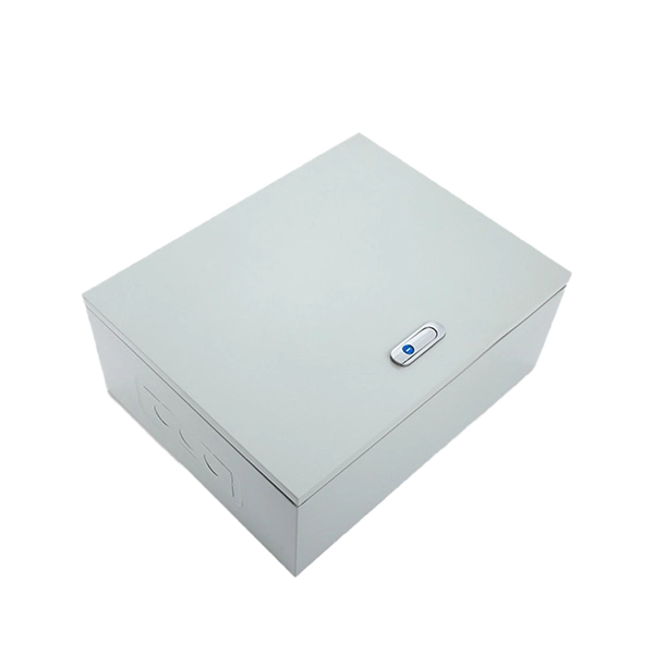
In this video, we'll walk you through the process of wiring a home distribution box with a detailed connection diagram. Whether you're an electrician or a DIY enthusiast, this guide will help you understand the basics of home electrical distribution. more Welcome to. This guide provides step-by-step instructions for connecting a distribution box and highlights key factors to consider during installation. What Is a Distribution Box? A distribution box, also known as an electrical distribution board, is a critical component in electrical systems. A distribution board or distribution box is where the main power supply is distributed to multiple loads. In this article, I'll teach you how to wire a Power Distribution Block (PDB) to distribute electricity from a single input source to multiple pieces of equipment in your branch circuit.
[PDF]
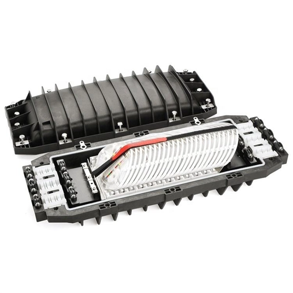
This schematic details the products and procedures for the treat-ment of construction joints/cold joints in new concrete structures. Cold joints occur when a fresh concrete batch is poured against a partially hardened existing layer. As you know, concrete hardens through chemical reactions between cement aggregate, water, and air. This detail uses two elements in addition to ad-ditives and coaings to waterproof. Cold jointing concrete is a technique used to connect two separate concrete pours that have not fully bonded together, often due to delays or interruptions in the pouring process. This method involves preparing the existing concrete surface by cleaning and roughening it, applying a bonding agent to. Eng-Tips is the largest forum for Engineering Professionals on the Internet. Members share and learn making Eng-Tips Forums the best source of engineering information on the Internet! Congratulations GregLocock on being selected by the Eng-Tips community for having the most helpful posts in the. Managing cold joints is an important concept to grasp when working on concrete projects. For the completed structure to be strong and long-lasting, cold joints must be handled correctly. The term "cold" is used because the two concrete layers are not bonded properly, which can result in a weakened.
[PDF]
Welcome to our channel! In this video, we'll walk you through the process of wiring a home distribution box with a detailed connection diagram. It serves as a central hub for distributing electricity throughout a building, ensuring that power is delivered safely and efficiently to all the required locations. And all the switching and protective devices are installed in the. Distribution Board or DB is an electricity supply system or a common enclosure that distributes the electrical power feed into subcircuits. It includes isolator, RCCB (Residual current circuit breaker) or RCD (Residual-current device) devices, protective fuses or MCB's (Miniature Circuit Breaker). That's why having a clear, detailed diagram of your home's distribution board wiring is essential. A distribution board (also known as a service panel or breaker box) is a centralized collection of circuit breakers, fuses, and/or relays used to control and protect the wiring in a home.
[PDF]
Picking up the best router for fiber internet isn't just about going to the market and choosing one of the best wireless routers. Instead, you need to carefully look at its specs, performance, and the type of securit.
[PDF]
We will look at how to interpret PLC LED status indicators for digital inputs and outputs and how to perform troubleshooting tests using a Digital Multimeter. This section includes the block diagram of the DI 16x24VDC ST module with the terminal assignments for a 1-wire connection. Information on wiring the BaseUnit can be found in the system manual ET 200SP distributed I/O system. The load group of the module must begin with a light-colored BaseUnit. How to wire real-world signals into the Logo's digital inputs to detect whether a machine is running. Covers stack lights, door sensors, relay contacts, and proximity switches — with a complete wire diagram and step-by-step instructions for both electrical engineers and IT teams. You have a Siemens. PLC and DCS control systems Wiring Diagrams for Digital Input (DI), Digital Output (DO), Analog Input (AI), and Analog Output (AO) signals. be responsible or liable for indirect or consequential damages resulting from the use or application of this equipment. The examples and diagrams in this manual are included solely for illustrative purposes. Because of the many variables and requirements. This manual contains information that is necessary to use the NX-series Digital I/O Unit. PLC programs rarely cause failures, so in this article, we'll assume that there are no program errors and that the fault originates in the.
[PDF]
Finally, we elucidate the latest developments and vital features of modern 850 nm VCSELs for high-speed interconnects. Introduction. Nedinsco delivers highly advanced optronic systems for reconnaissance and surveillance, trusted by military forces worldwide. Equipped with next-generation sensors, our systems significantly enhance visibility. We offer solutions for armored vehicles, unmanned ground vehicles (UGVs), drones (UAV's). Our company's advanced optoelectronic systems represent a technological leap forward in border security capabilities. Introduction Since the invention of the VCSEL by Iga's group in 1978 [1, 2] and the demonstration of its first room-temperature (RT, 300 K) operation in 1988 , many groups. Northern Macedonia has purchased three mobile surveillance and surveillance systems from the MUSON – MUSON 20FM series, developed by the Bulgarian company Opticoelectron, reports the BulgarianMilitary. Customized payload features, as well as FOG based stabilization provides ultra-long-range observation and tracking capabilities. The basic instruments like: VIS day camera, low light, SWIR camera, LWIR or. High-speed optoelectronics is central to many important developments in the communication, computing, sensing, imaging, and autonomous vehicle industries. With a sharp rise of attention on energy efficiency, researchers have proposed and demonstrated innovative materials, high-speed devices, and.
[PDF]
In practical applications, there are many electrical connection methods for industrial power distribution boxes, which will be introduced below. Primary distribution systems consist of feeders that deliver power from distribution substations to distribution transformers. Many feeders leave substation in a concrete ducts and are routed to a nearby pole. At this. Proper sub panel wiring is a fundamental skill for any licensed electrician, critical for safely expanding a building's electrical capacity. The process involves installing a secondary breaker panel fed from the main service panel. Key compliance points include performing an accurate panelboard. Four basic circuit arrangements are used for the distribution of electric power: radial, primary selective, secondary selective, and secondary network circuit arrangements. A busbar is a large-section conductive. The Secondary Distribution Box (SDB) receives power from Main Power Distribution box via an extender cable and provides a central power distribution to feed normal branch circuits to the electric floor modules through snap-on extender cables. The SDB can be fitted with terminal blocks for custom. Small electrical installations normally have only one distribution board, connected directly to the main service, and appliances are powered with branch circuits protected by breakers. However, powering all loads from the same distribution board is impractical in larger installations, since the.
[PDF]
For fiber optic internet speeds of 100 Mbps or higher, a router supporting at least 1 Gbps is required. Look for routers with AX or AC designations (Wi-Fi 5 or 6) that support faster speeds than older N standards (Wi-Fi 4). Your router must have a Gigabit Ethernet WAN port to connect to the ONT. Routers designed for DSL (which uses phone line inputs) or cable (which uses coaxial inputs) won't work. Some fiber internet plans. This guide comprehensively answers that, exploring the technicalities, benefits, and practical steps involved in using your existing router with a new fiber connection, ensuring you make an informed decision. Is Your Existing Router Actually Fiber-Ready? Fiber optic internet represents a. Yes, you can often use your existing router with fiber optic internet, but there are crucial considerations. Understanding compatibility, potential limitations, and when an upgrade is necessary will ensure you get the most out of your high-speed connection. However, the market is flooded with countless options, making the selection quite overwhelming. To simplify. Also, try switching up the wireless channel on your router since interference from other devices can slow things down. Another thing to check is if your router's firmware is up to date. Routers perform several key functions: Data Routing: It directs data between your devices and the internet. Network Management: It manages and prioritizes network traffic.
[PDF]
The optocoupler can be used in many different applications as an interface between low voltage digital, such as 3. 3V logic, or 24V control circuits and large mains power electronic devices. Thus protecting sensitive circuits (e., microcontrollers) from high-voltage supplies. Optocouplers, also known as opto-isolators, uses infrared light to transfer electrical signals between two electrically isolated circuits and are commonly classified by their photosensitive output device What is an Optocoupler? An optocoupler (also called an opto-isolator, photo-coupler, or optical. Optocouplers become specifically useful where an electrical signal is required to be sent across two circuit stages, but with an extreme degree of electrical isolation across the stages. Optocoupling devices work as logic level changeovers between two circuits, It has the ability to block noise. An opto-isolator (also called an optocoupler, photocoupler, or optical isolator) is an electronic component that transfers electrical signals between two isolated circuits by using light. Opto-isolators prevent high voltages from affecting the system receiving the signal.
[PDF]

A good laser source for a singlemode link will have a power output of ~ +3 to +6 dBm - 2-4mw - coupled into the fiber. Tx power (transmission power) refers to the intensity of the optical signal output by the transmitting end of the optical module. However, in practical use, we adopt the average Tx power. These modules, including SFP, SFP+, and SFP28, are widely used in enterprise networks, data centers, and carrier-grade deployments. Optical loss is measured in “dB” which is a relative measurement, while absolute optical power is measured in “dBm,” which is dB relative to 1mw optical power Loss is a negative number (like –3. 2 dB) while power measurements can be either positive (greater than the reference) or negative (less than. SFP (Small Form-Factor Pluggable) modules are compact transceivers that allow for high-speed communication between network devices. They are essential in applications like telecommunications, data centers, and enterprise networks. Generally, the power levels are specified in terms of transmit (TX) power and. Transmit power is the power at which the transmitter of an optical transceiver module transmits optical signals in dBm. When the signal received is outside of the range, there is a.
[PDF]